Flettner fl265
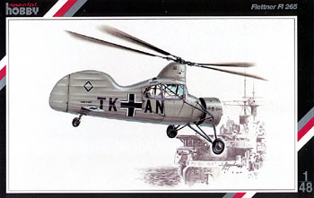
A short run kit from Special Hobby of the Flettner 265. I’m just going to quote from wikipedia
“This helicopter, developed in 1938 with the support of Nazi Germany‘s Kriegsmarine, made it possible, for the first time, to transition from powered rotary-wing flight to autorotation and back again, making it the safest helicopter of its time. In contrast to the Fl 185, the Fl 265, believed to be the pioneering example of a synchropter, had two intermeshing rotors 12 m in diameter, powered by a 160 hp (119 kW) BMW-Bramo Sh 14 A radial engine in the nose of the fuselage, fitted with a fan to assist cooling. Six helicopters were constructed, but series production was curtailed in favour of the Flettner Fl 282.[“
Here’s an interesting video showing the fl265 flying https://www.youtube.com/watch?v=SbeRRCrn-y8
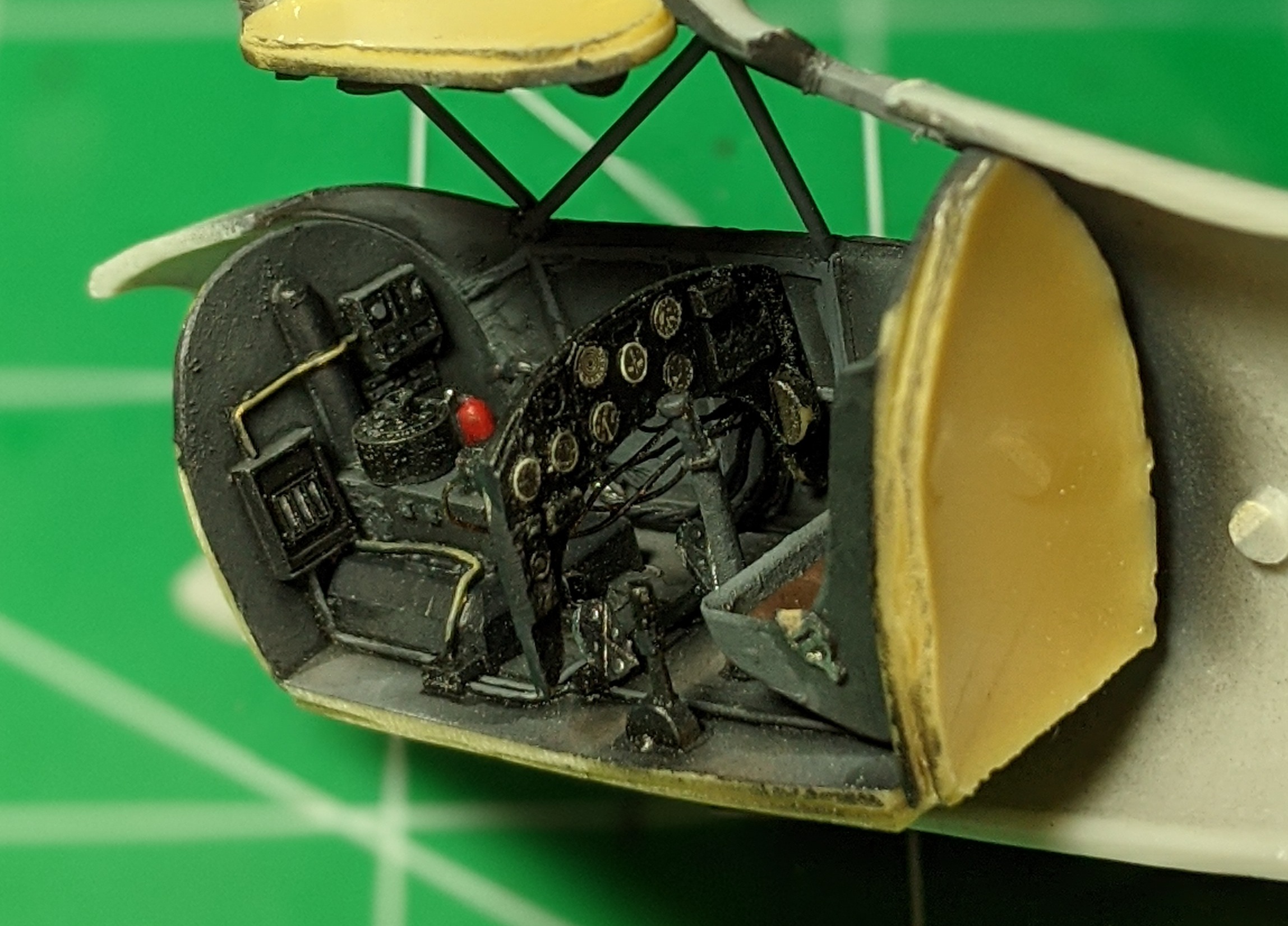
This kit is your typical short run kit – thick moldings, no location pins, vacuum formed wind screen, resin interior, and questioinable ‘buildable’ items. lets start with the nicely detailed resin interior, that has the seat with belts and the engine cast together.
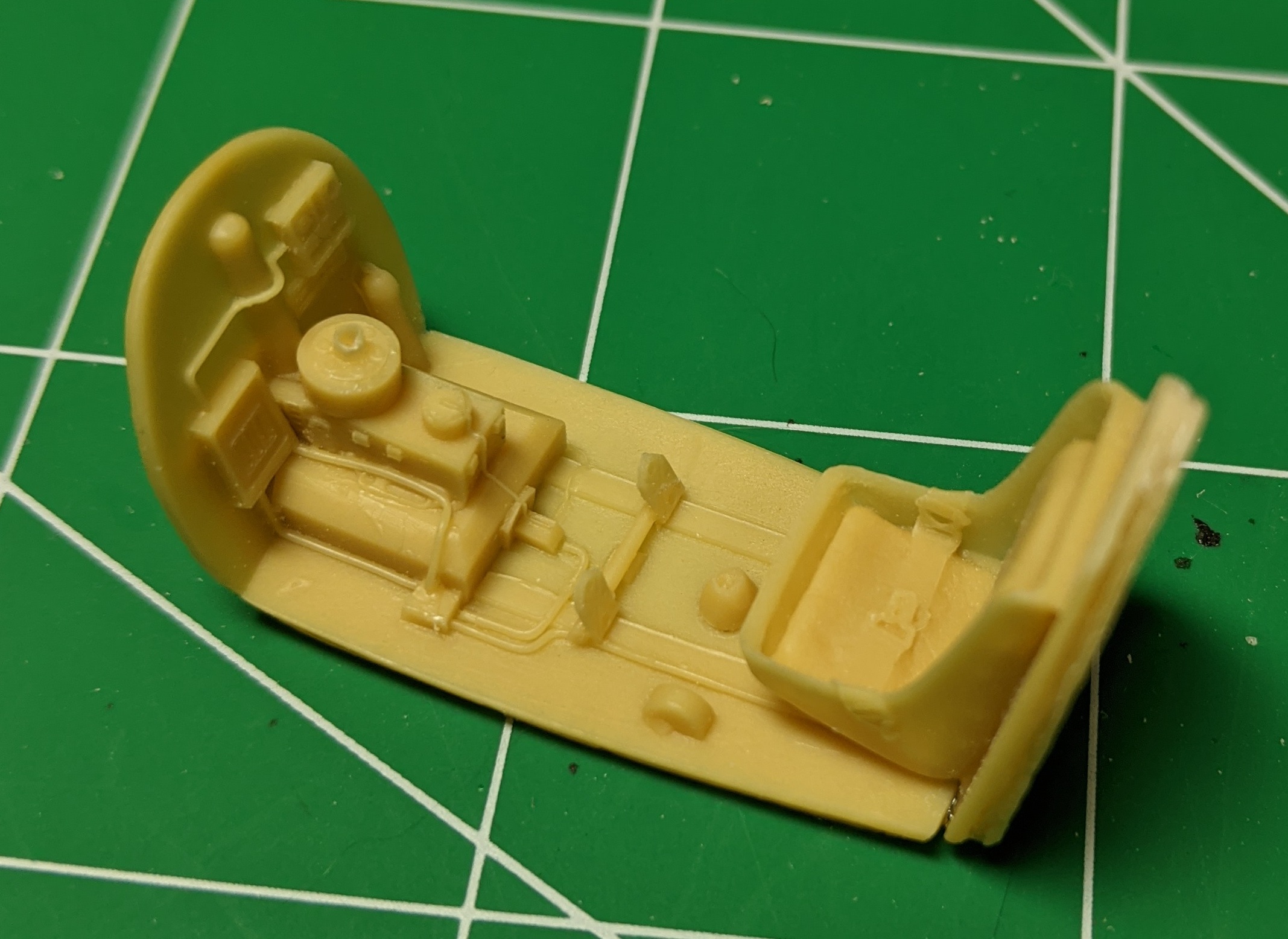
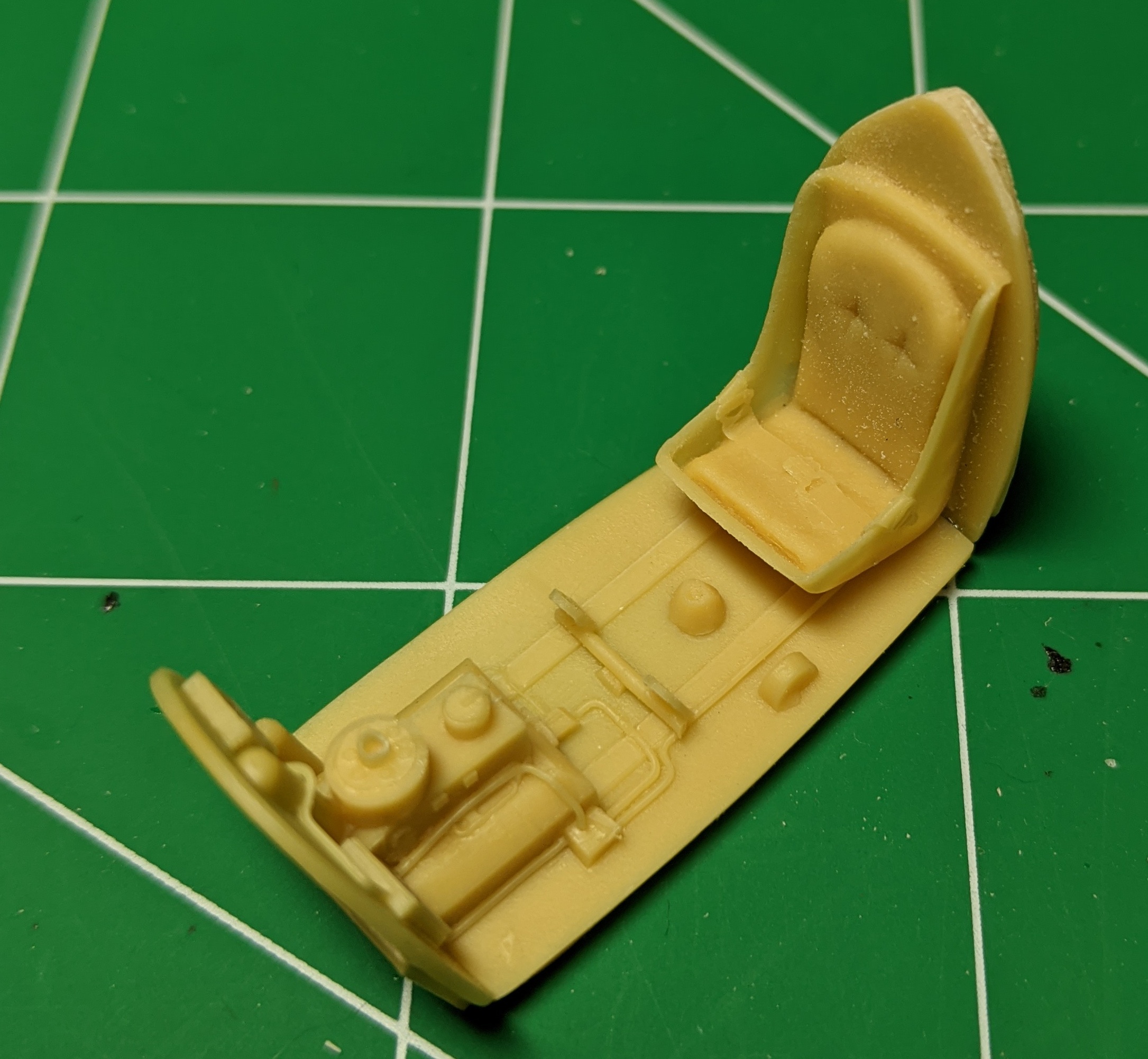
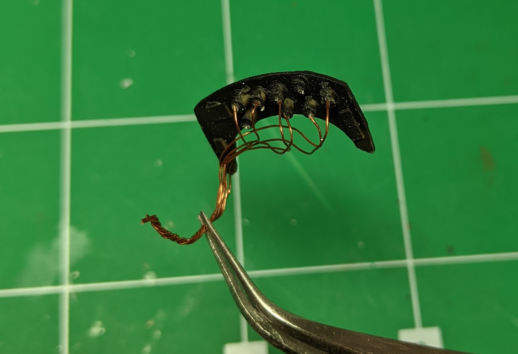
Just careful painting will create a very nice representation of the cockpit. I used some punched out decals for the fight panel details, and since the back is completely viewable, I added some thick sprue for the instrument backs with thin copper wiring.
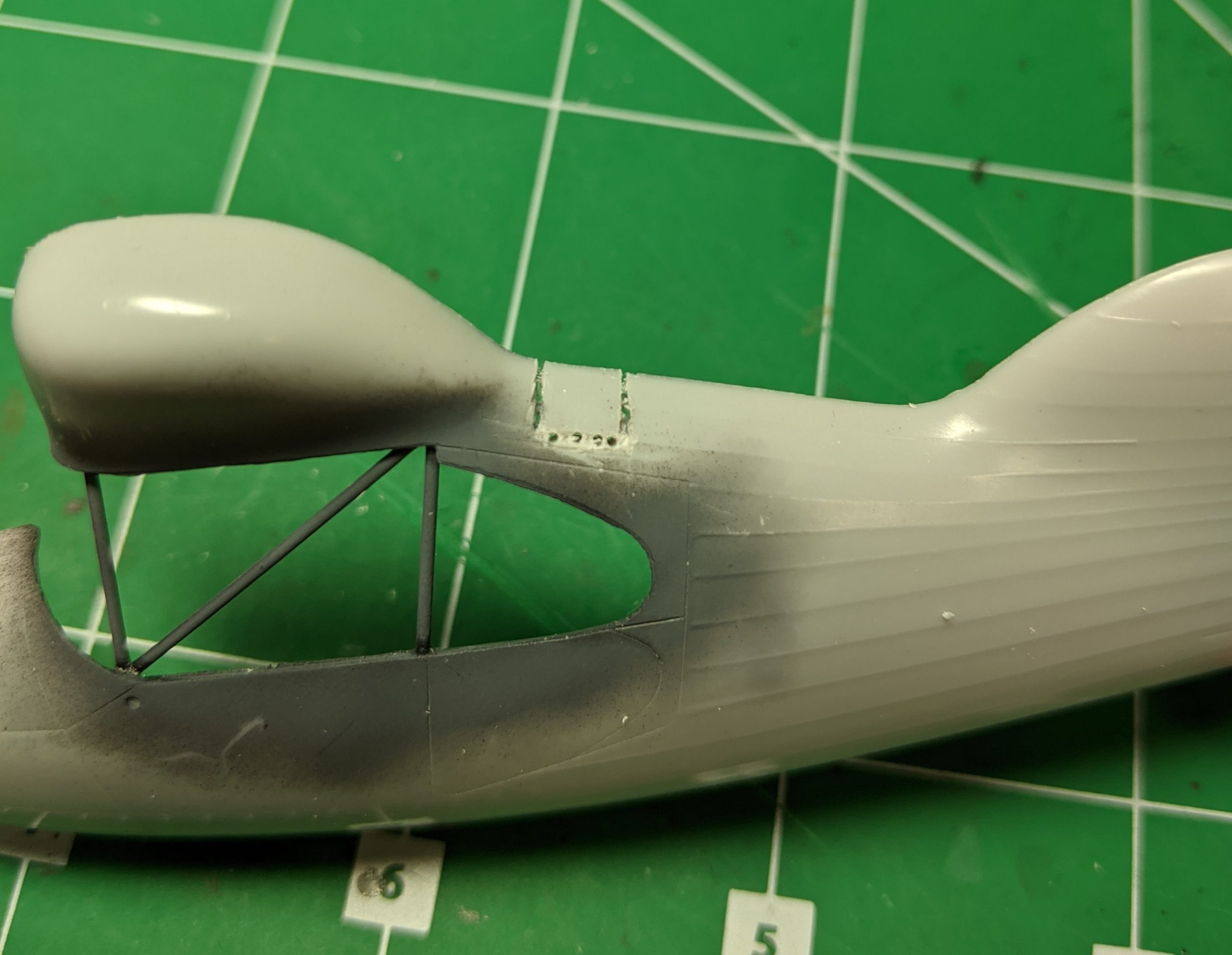
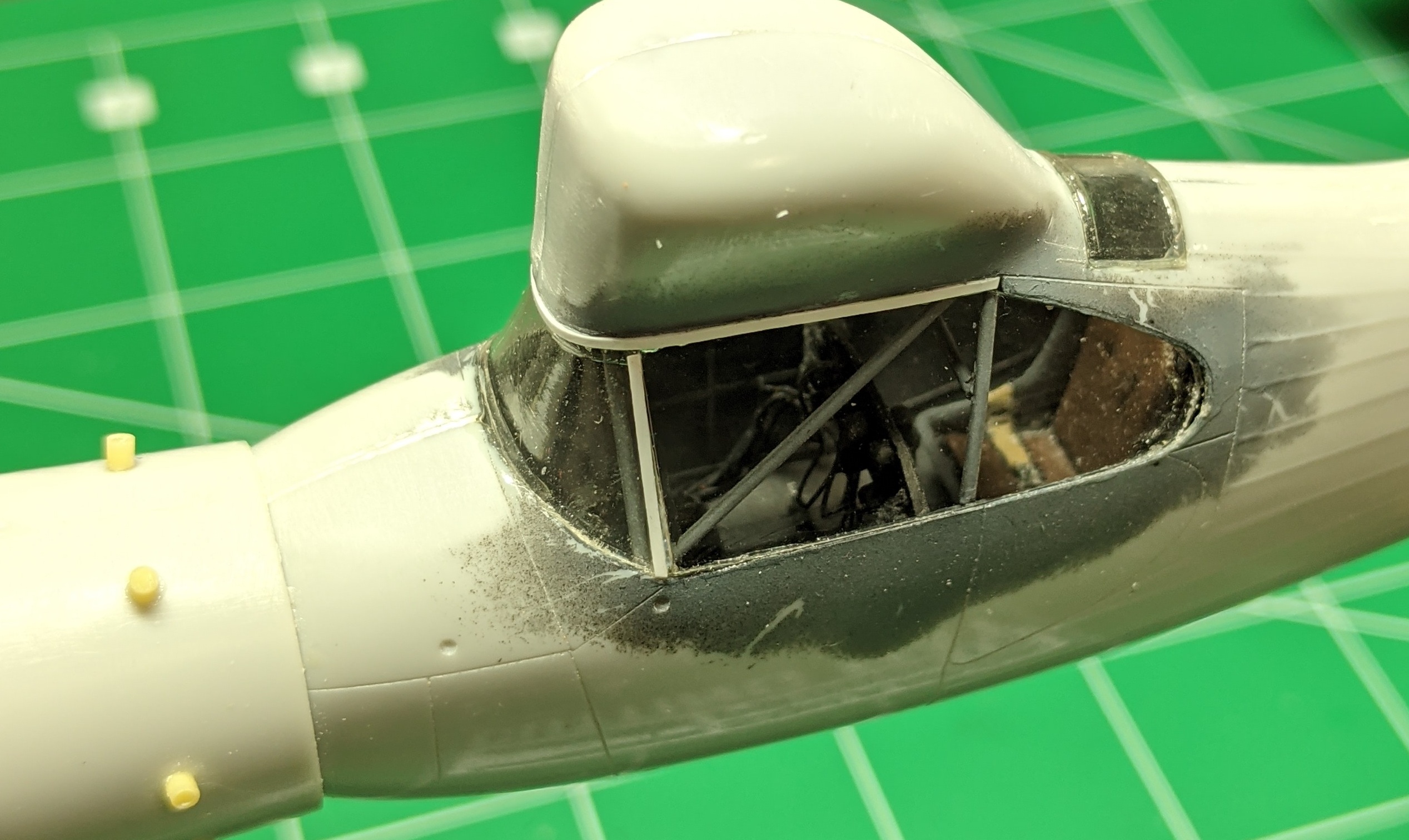
Next is the framing around cockpit which is missing and was built using some styrene rod.
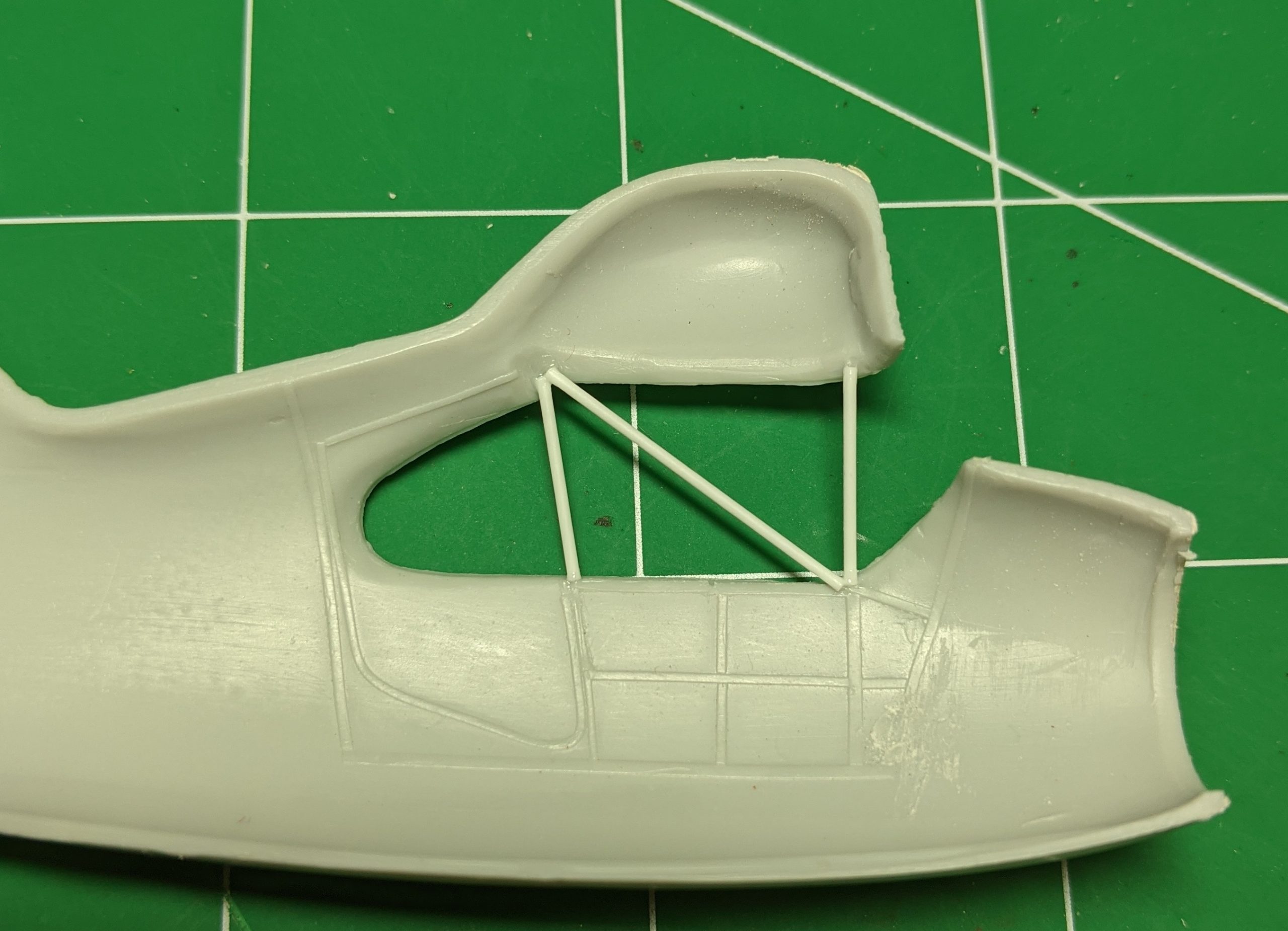
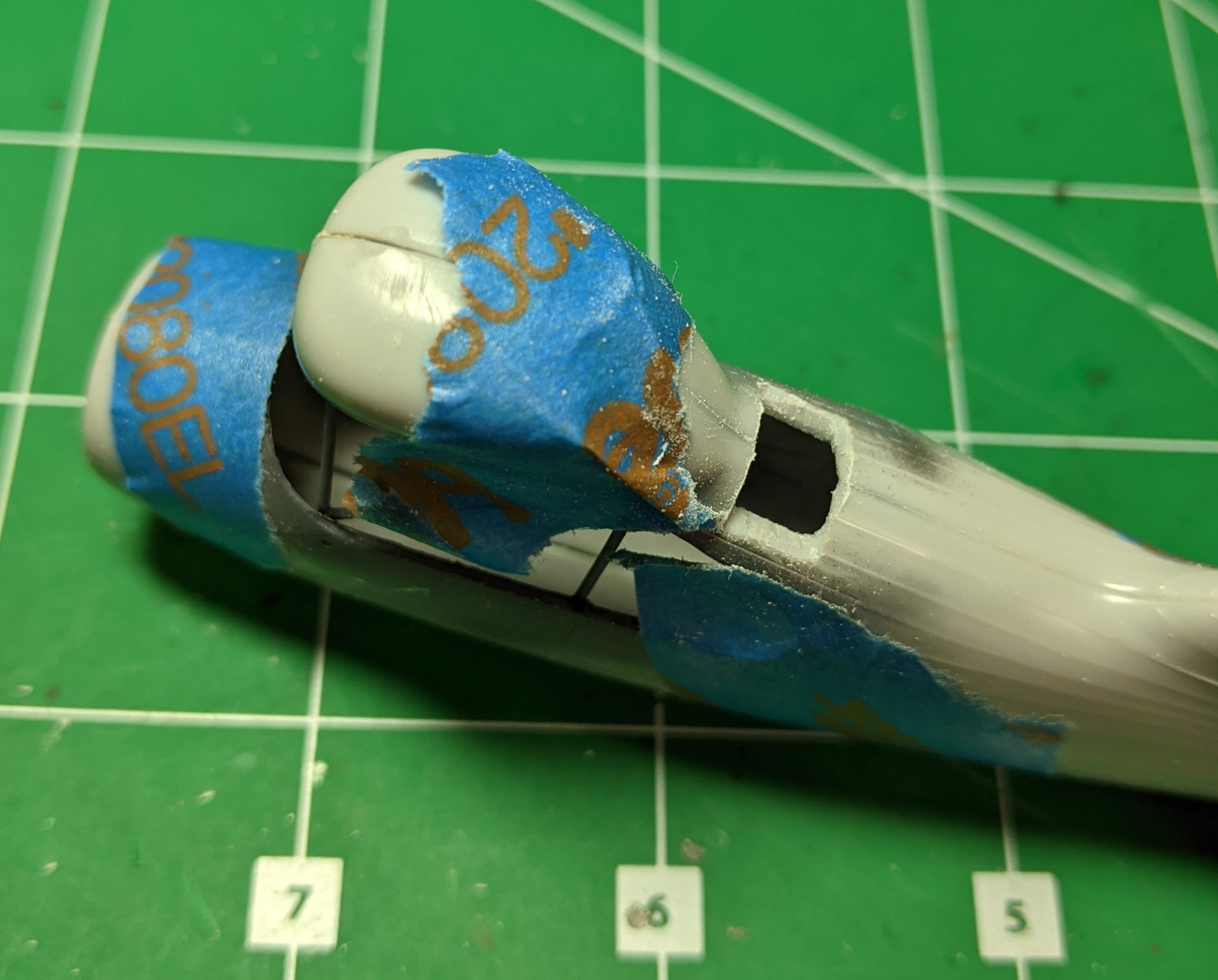
There is a top window which is molded shut and have to be opened up. Some chain drilling followed by a x-acto knife did the trick, but the plastic is very, very thick in this location, and have to be significantly thinned to make it look acceptable.
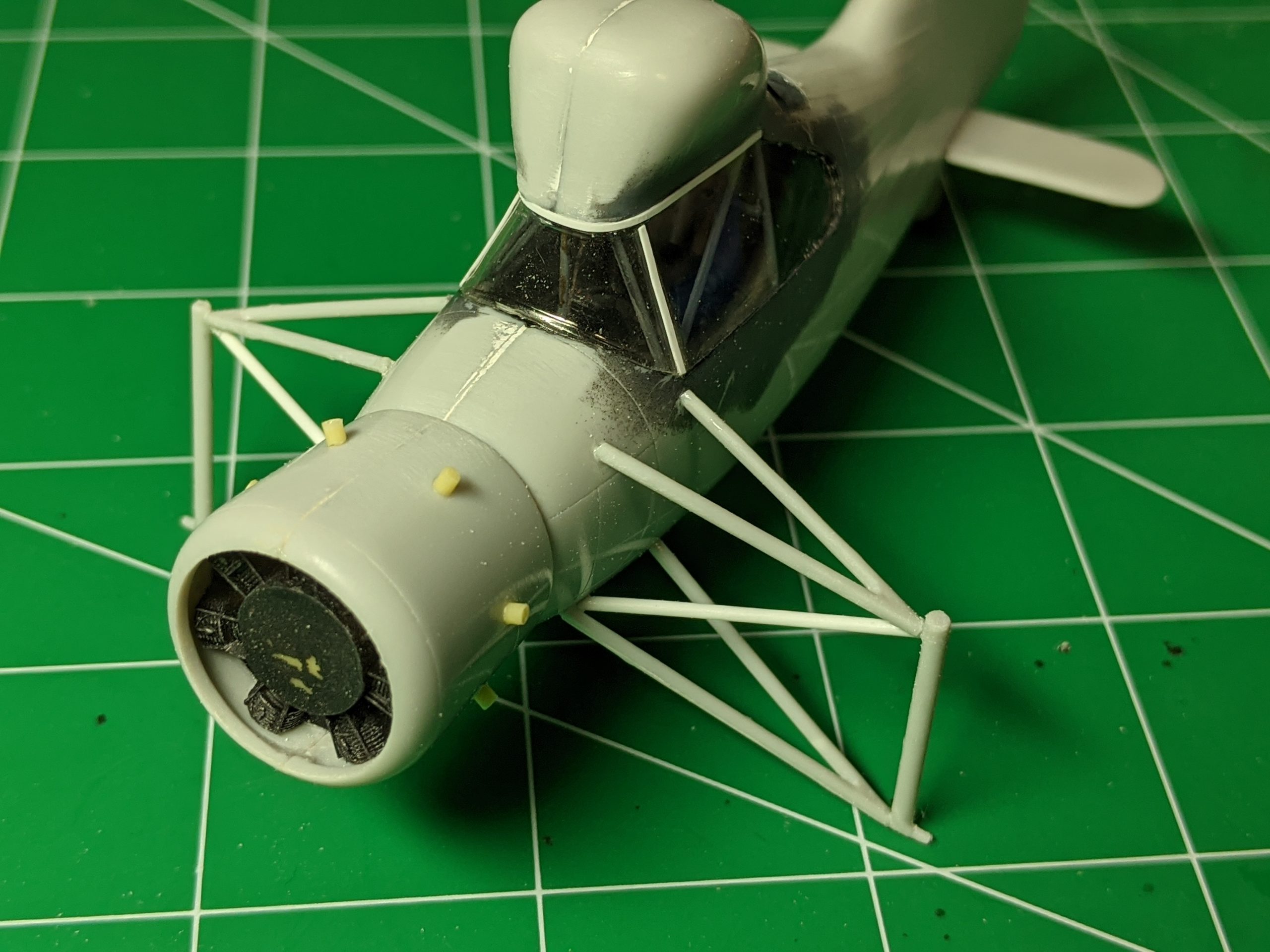
Here’s the cockpit fully installed along with the rotor mechanism glued to the top of the aircraft.
Here’s the model closed up with the vacuum formed windscreen installed. There was some significant gaps and missing details, which was added with styrene strips and rod.
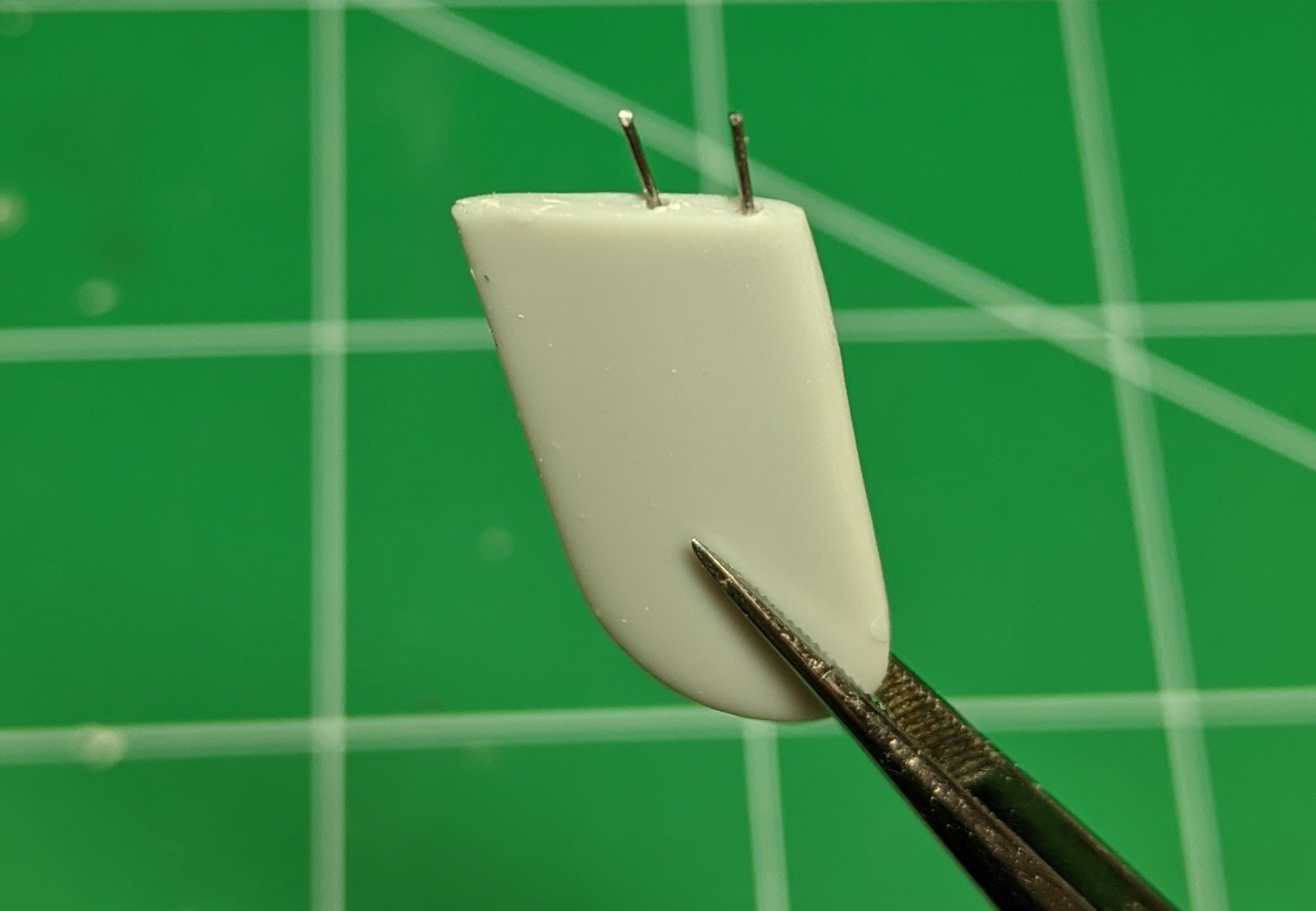
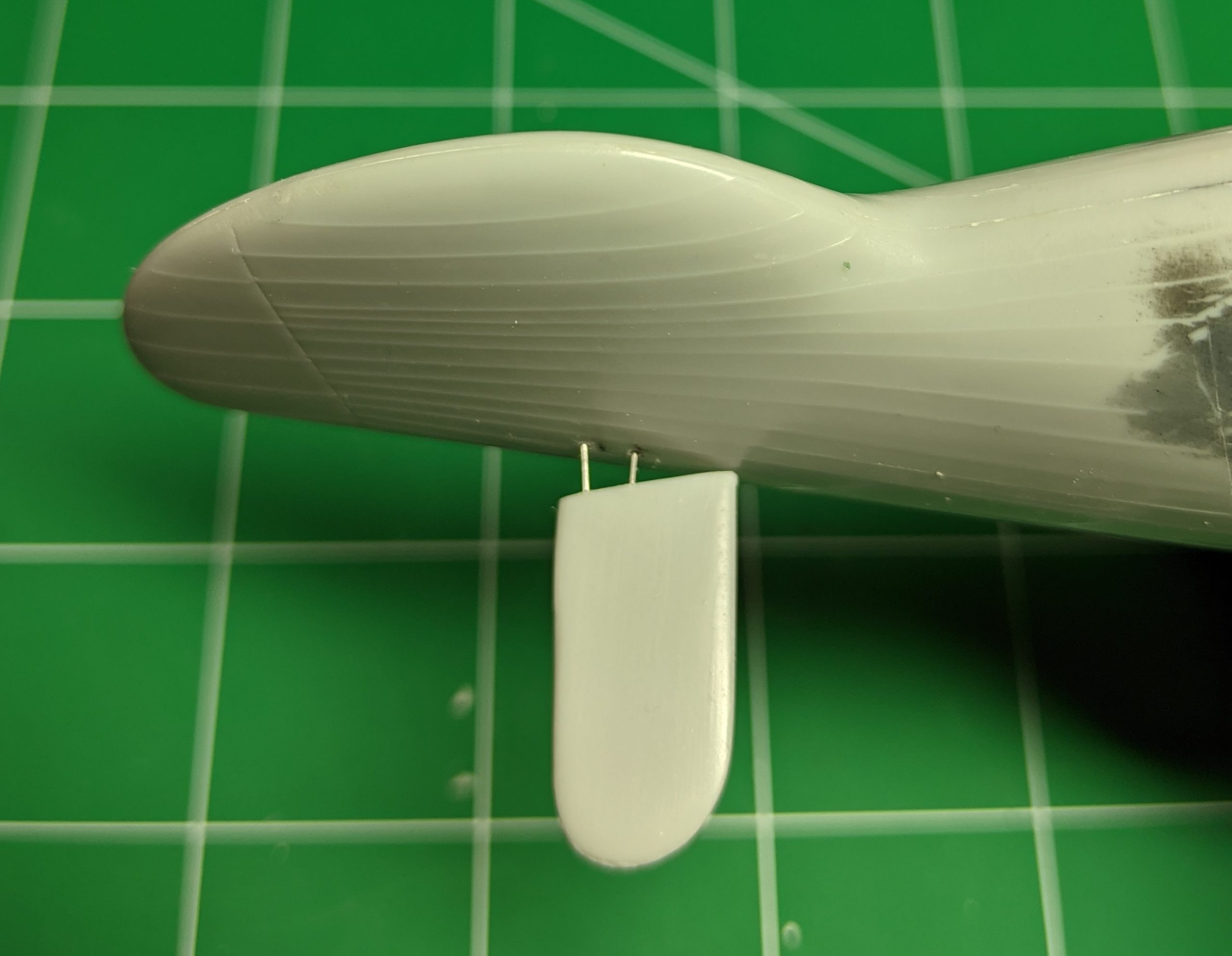
The rear stabilzer has no locating pins, so I used paper clips to create my own for a strong joint.
The engine has small resin ‘exhausts’ (?) that needs to be installed, probably a little too long and should be shortened. The wheel support is a fairly fragile set of rods, whose lengths dont quite all fit and I replaced some of them with styrene rods. You can see the engine, which doesn’t have much detail, but it will be 90% hidden once finished.
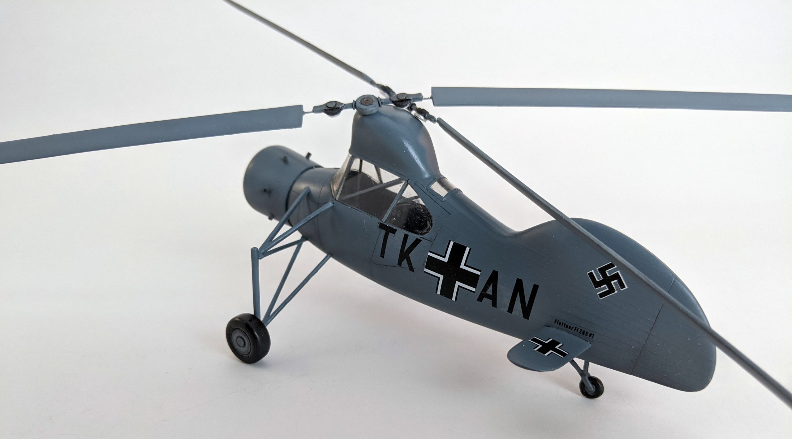
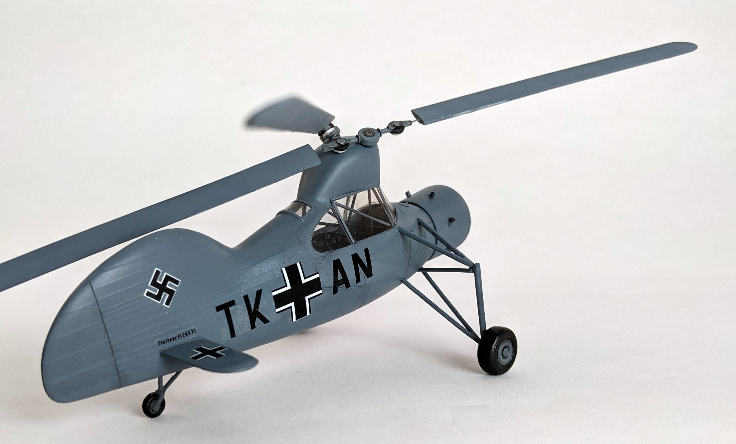
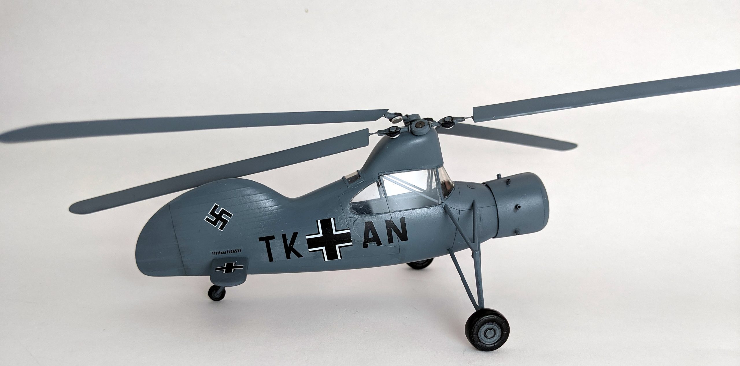
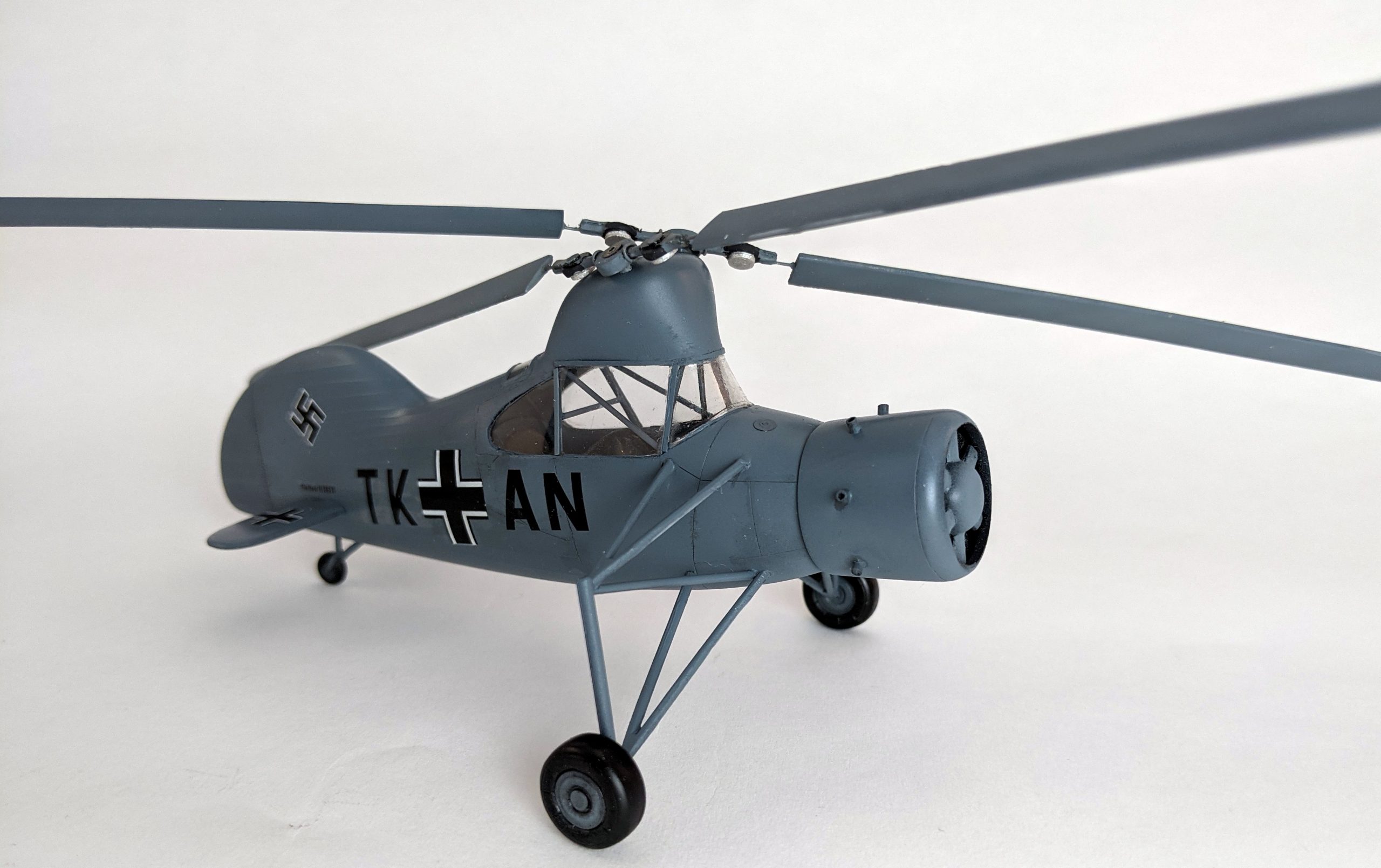
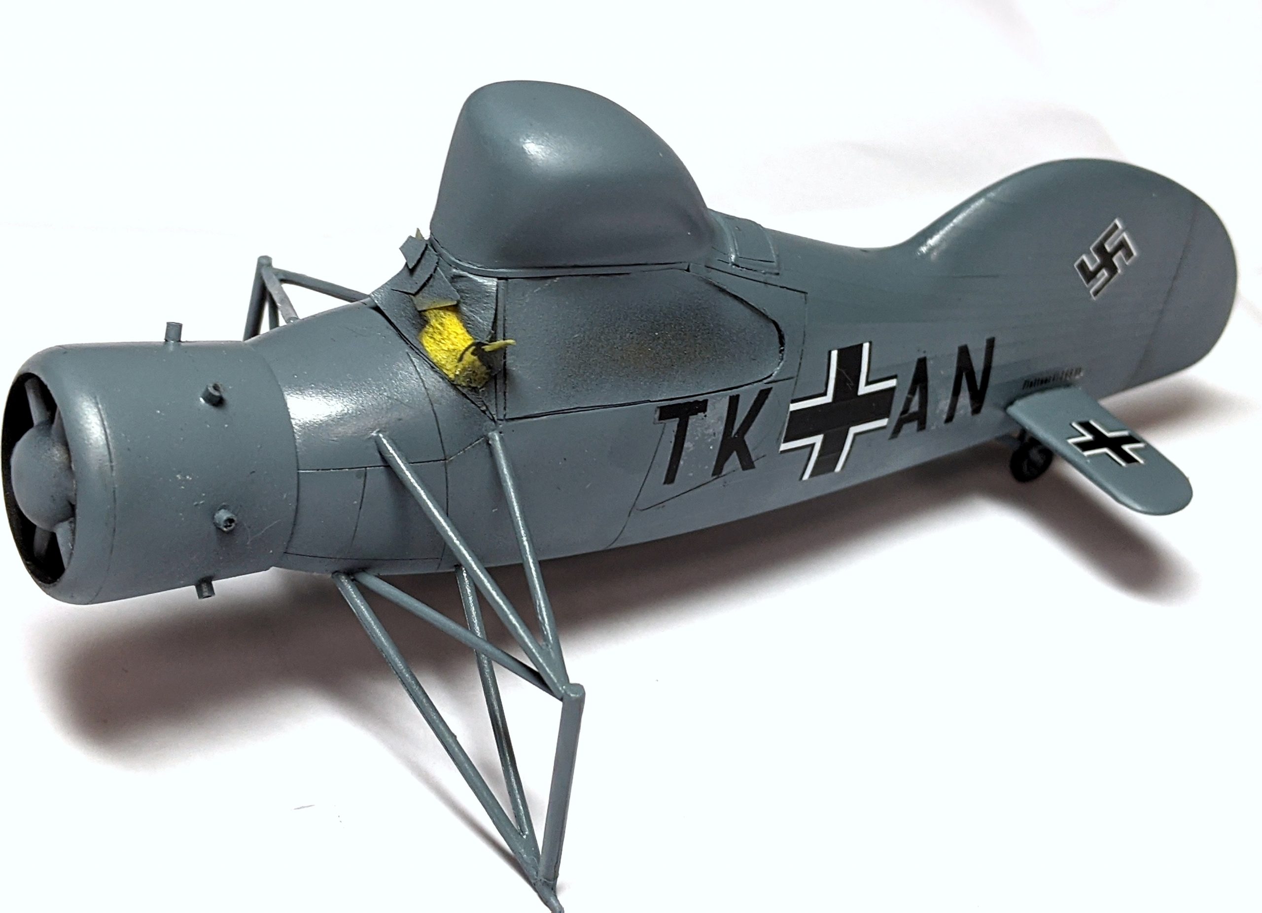
Here’s the main body painted and decaled.
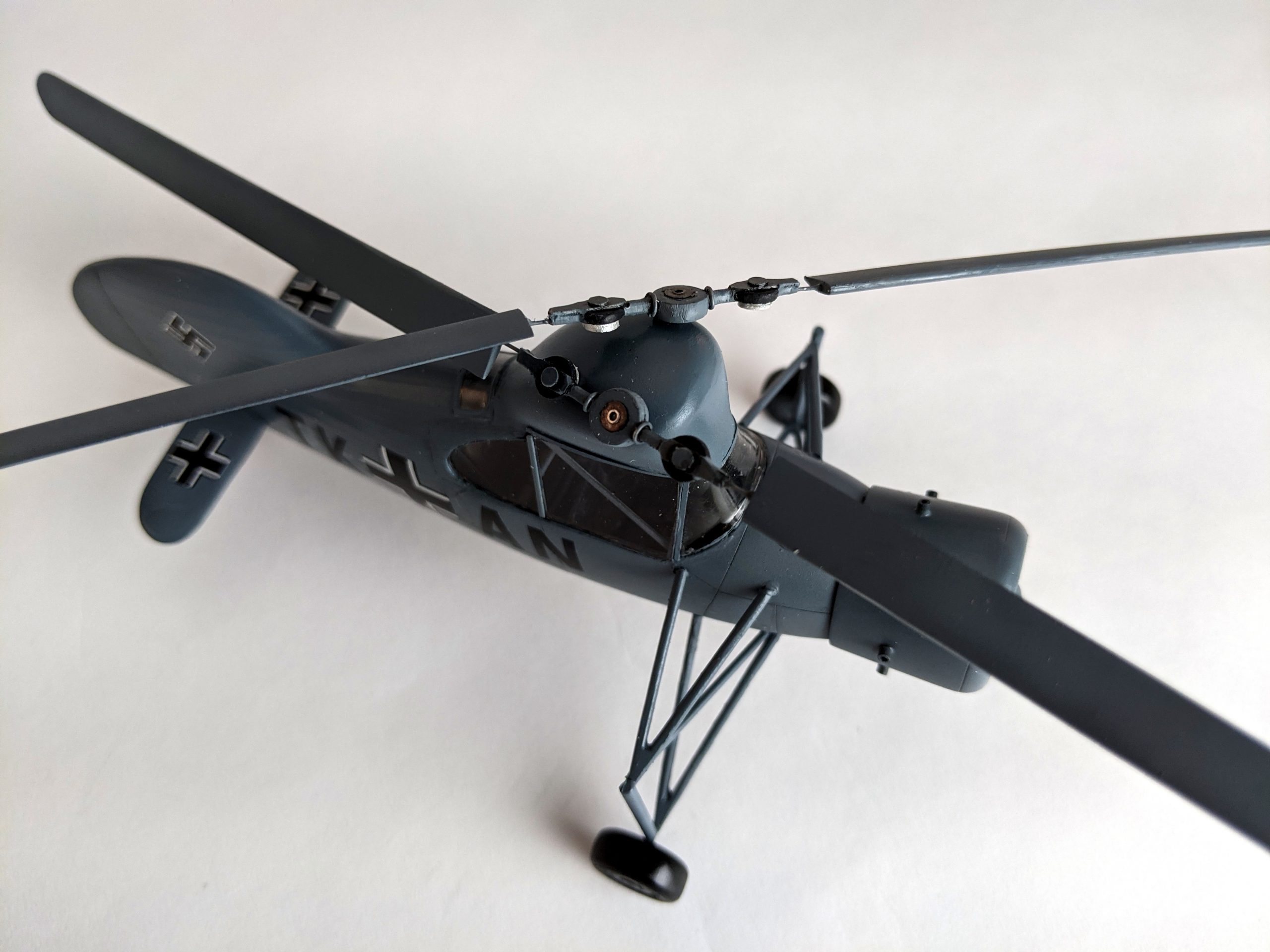
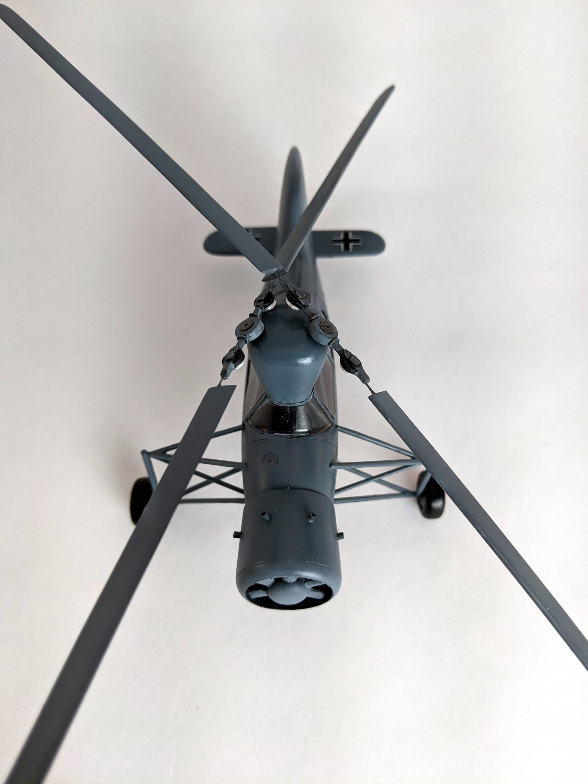
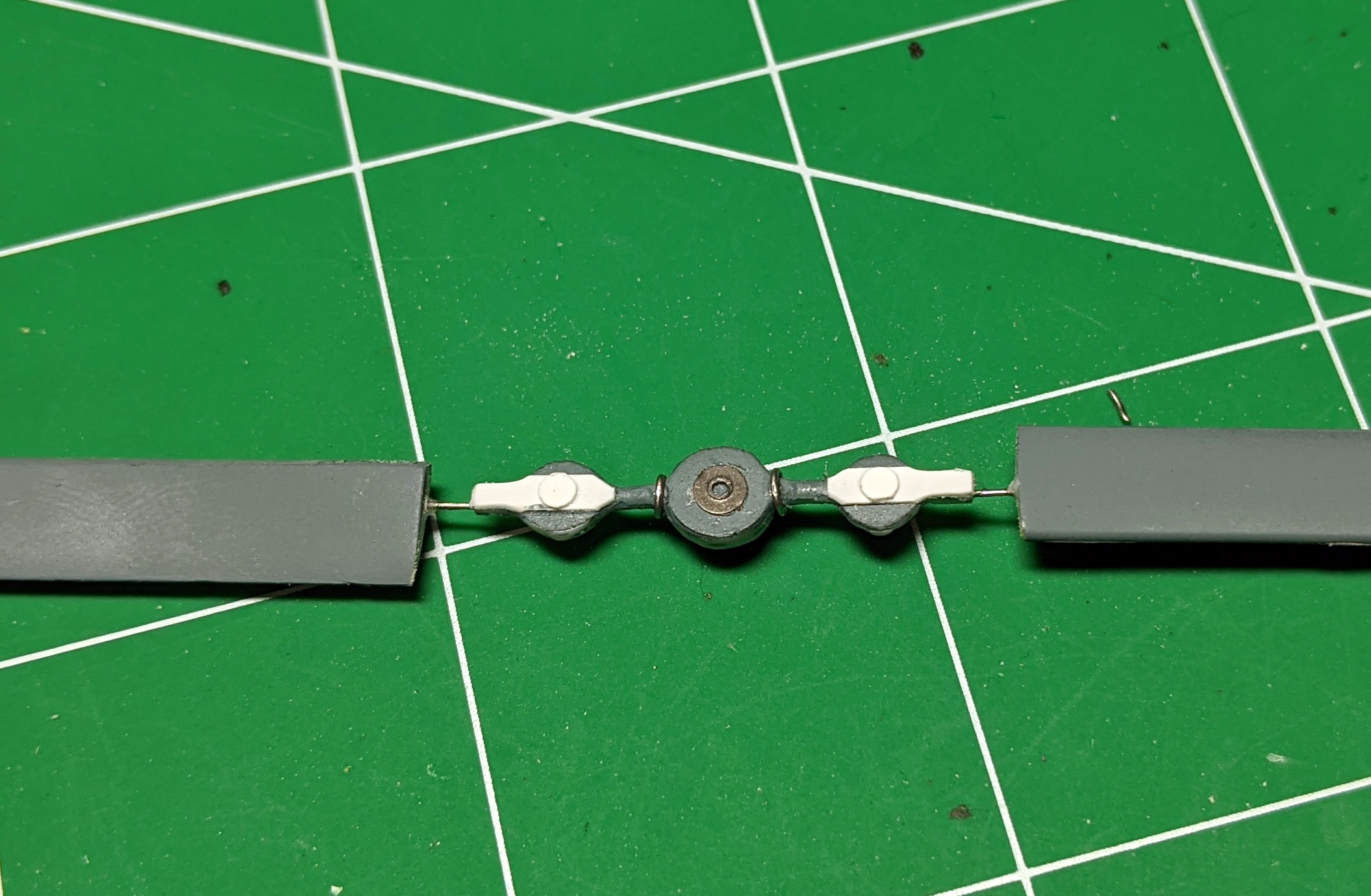
The final part was what I was dreading, the delicate rotors that was suppose to butt-join to the coupling. No way that will hold long term, and it’s divoid of all details. Just some round disks, so that just wouldn’t do. Based on reference photos, I used solder, spare PE, and plastic sheets for details. Again, ping were added as strong mating areas for the rotors,
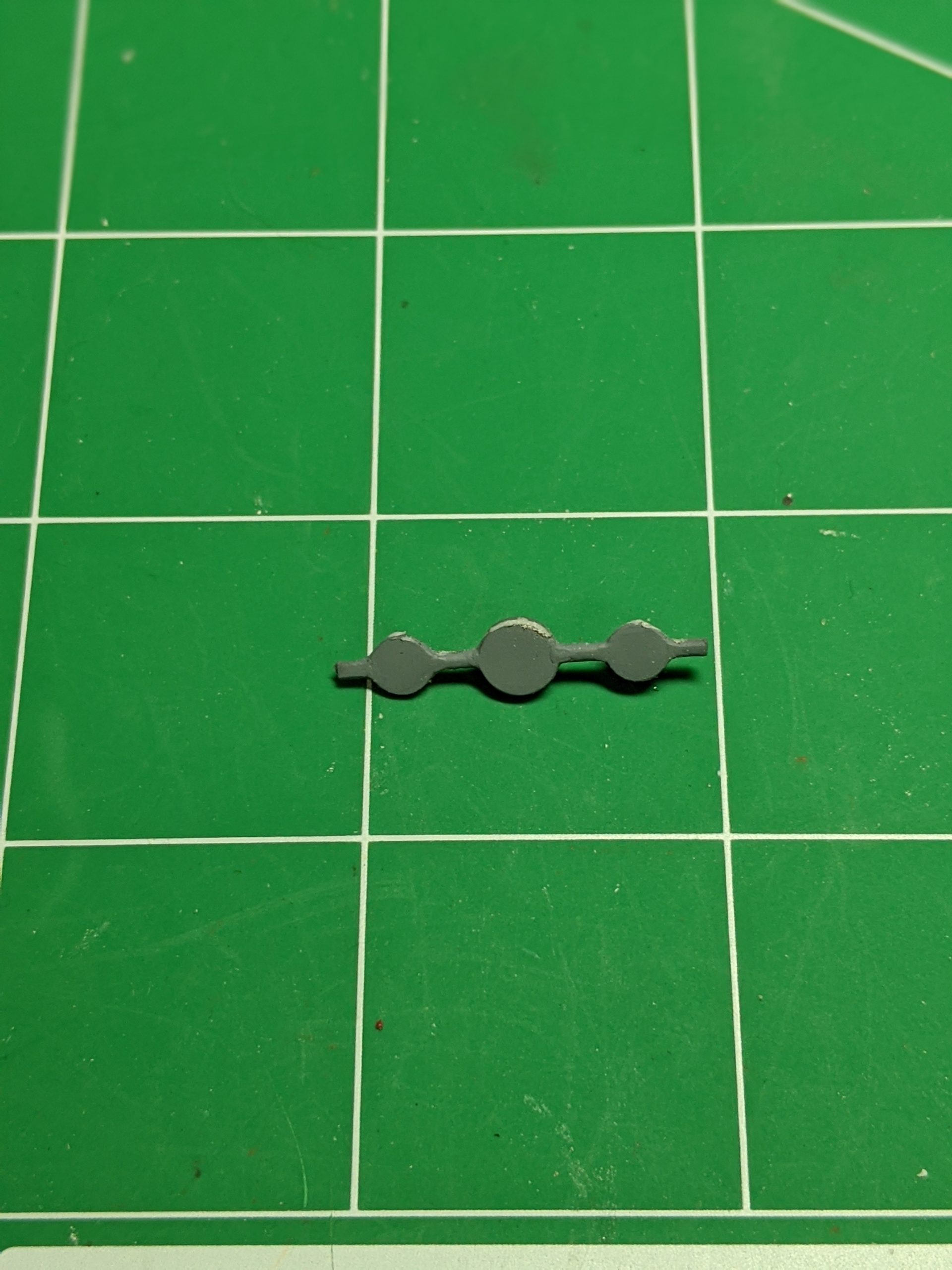
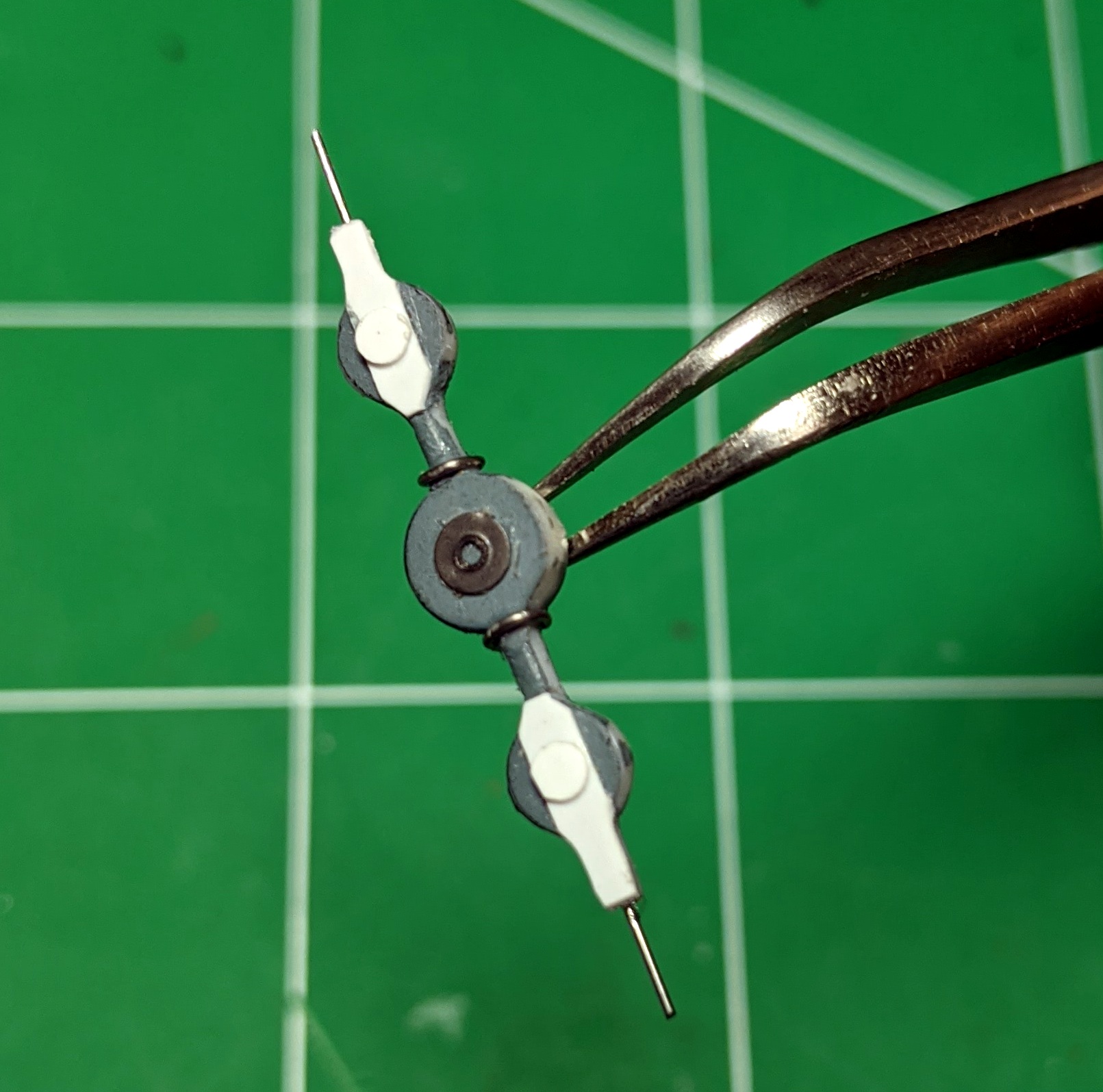
After drilling matching holes in the rotor and attaching with CA glue, a much stronger piece was created.
The final step was attaching the rotors, which itself is a bit precarious, but at the end a very unique item to my collection.