Messerschimt bf-110E – Eduard
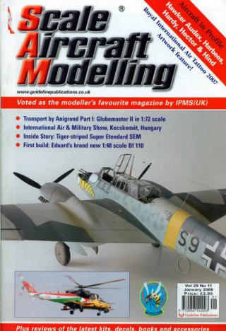
Eduard’s 2007 release. This was built as a review for Scaled Aircraft Modeller Jan 2008 Issue
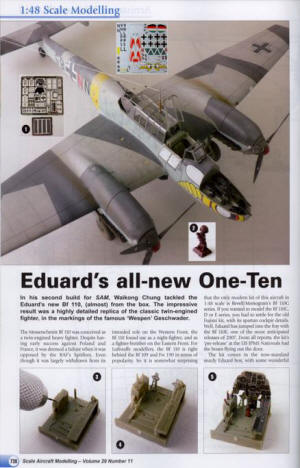
The Messerschmitt bf110 was conceived as a twin engine heavy fighter. Despite having early success against Poland and France, it was deemed a failure when it was opposed by the RAF Spitfires. Even though they were largely withdrawn from its intended role in the Western front, it saw its potential as a night fighter and as a fighter bomber on the Eastern front. For Luftwaffe modelers, the bf110 would be right behind the bf109s and fw190s in terms popularity. So it’s somewhat surprising that in 1/48th scale, the only modern kit of this aircraft is Revell/Monogram’s G series. If you wanted to model the C, D, or E series, you had to settle for the old Fujimi kit with its spartan cockpit details. Well, Eduard has jumped into the fray with the bf100 E, one of the more anticipated releases for 2007 in September. From all reports, the kit’s ‘prerelease’ at the US IPMS Nationals had the boxes flying out the door.
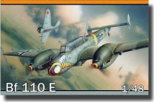
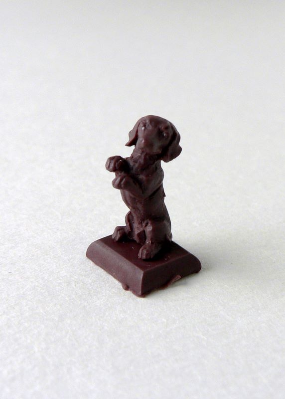
The kit comes in the now standard Eduard sturdy box with some wonderful box art of the 110 in Wespen nose markings going against a P-16 over the Eastern Front. Upon opening the box, you will be greeted by over 300 parts in the gray-green plastic. The details are fine and restraint, no sink marks or defects, just some flash in some smaller parts. The high parts count is somewhat deceiving in that there are many unused parts. More than half of Sprue D is unused, which means a bunch of nice fuel tanks and rocket tubes for your spare box. These parts are all slated for future releases. As this article was being written, Eduard already announced the C model kit. There’s even a ‘dachshund’ belly fuel tank on one of the sprues, so you know a D model will also be available sometime in the future. In addition you have two clear sprues for the canopy, with different parts to pose the canopy open or close. There are also two PE frets, one of which is in color.
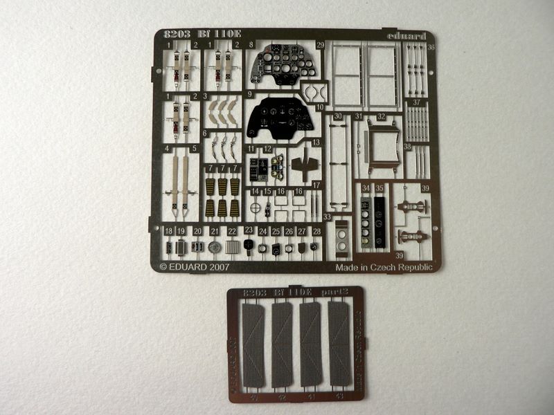
These are all meant for enhancing the cockpit. If you are one of those who don’t like PE’s, Eduard has provided the instrument panel with raised details in plastic. There’s also a decal sheet which allows five different aircrafts to be built along with full stencils . 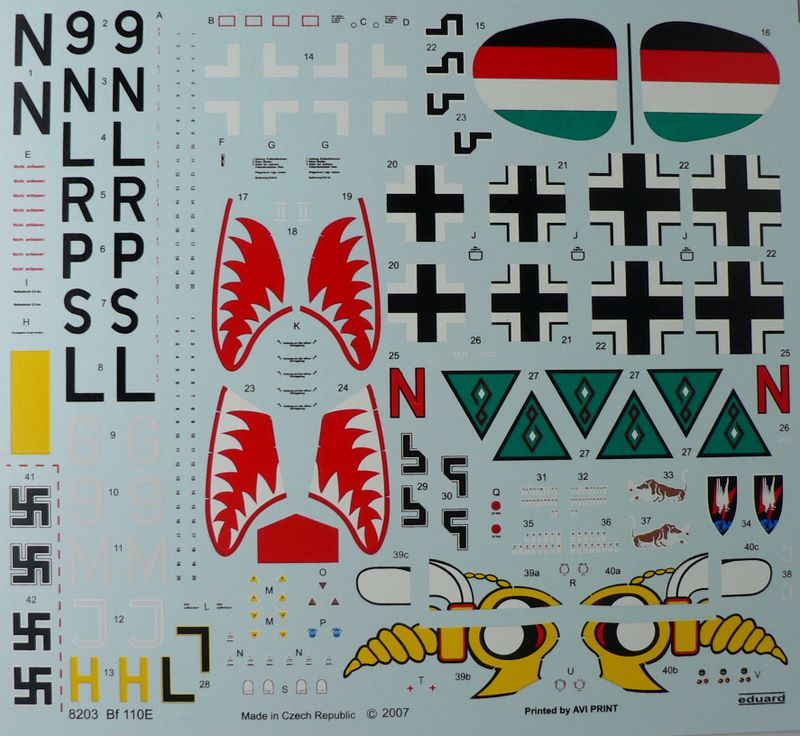
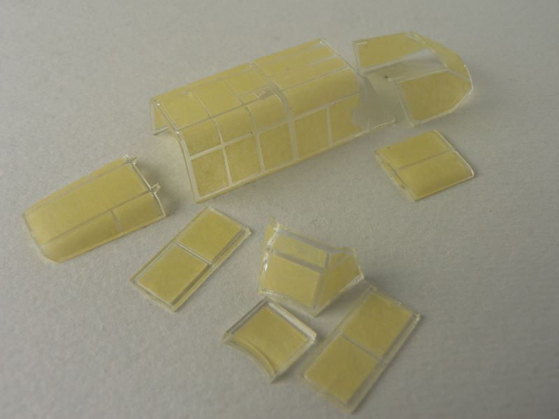
Masks are provided for the canopy, which is a real time saver for this particular aircraft. Finally, a resin dachshund is provided just as an extra. They actually come in three different poses, but each kit will randomly contain one of these. The instructions come in a 20 page glossy booklet with a brief history and five pages of full color for markings and stencil. A very impressive package indeed when you first open this box.
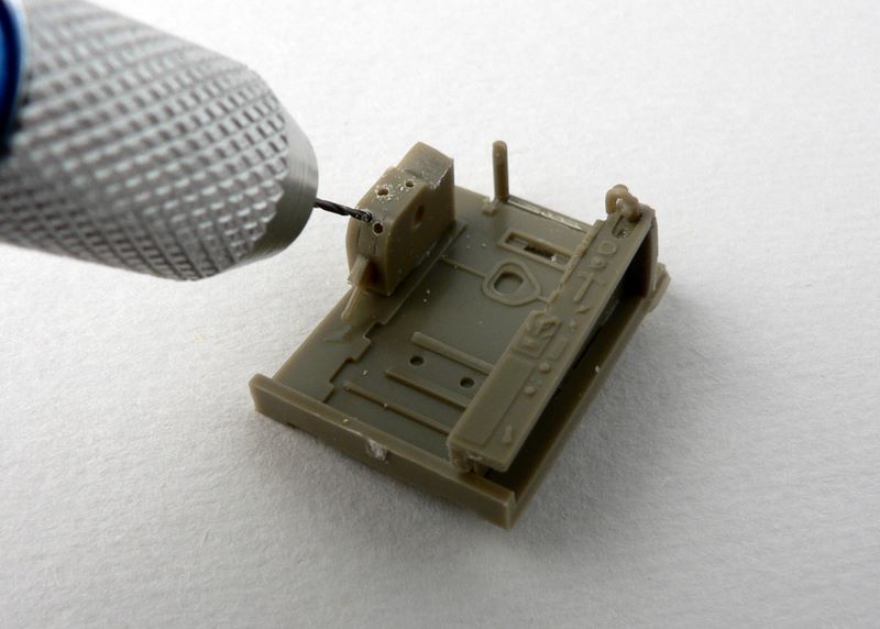
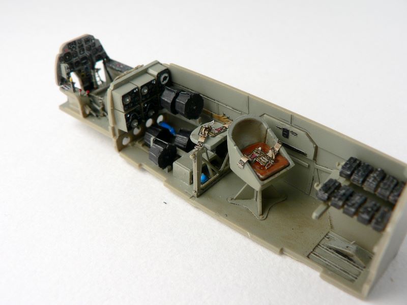
Following the directions, I started with the cockpit’s pilot area. As you build the side panels, you will immediately be faced with some very small parts. Eduard has wisely decided to use plastic instead of PE for parts that require a more 3-dimensional representation. To overcome the shortcomings of injected plastic vs. resin, they have separated out many parts which would usually be molded together. A good example is the throttle where each throttle lever is a separate piece. Along with PE, this little item of equipment is comprised of 7 pieces. When first faced with the levers, I realized that there were no locating holes and there was no way these pieces will stay intact during the build. So I drilled holes into the hosing with a pin vise to allow a stronger bond. The pedals are offered in plastic or in PE, which are much more detailed and finer in appearance.
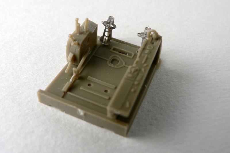
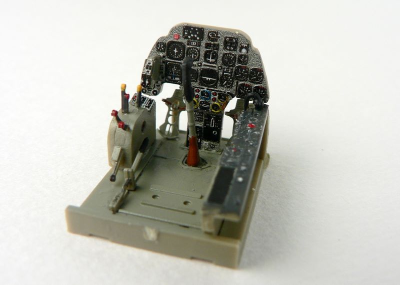
This combination of using each material to their best advantage can be seen even before the cockpit is painted. If you use the colored PE instrument panel, it actually comprises of 6 separate pieces glued on top of a blank plastic panel. Some care and patience with gluing and PE folding will be required, but when installed next to the painted throttle shows that the effort is well worthwhile
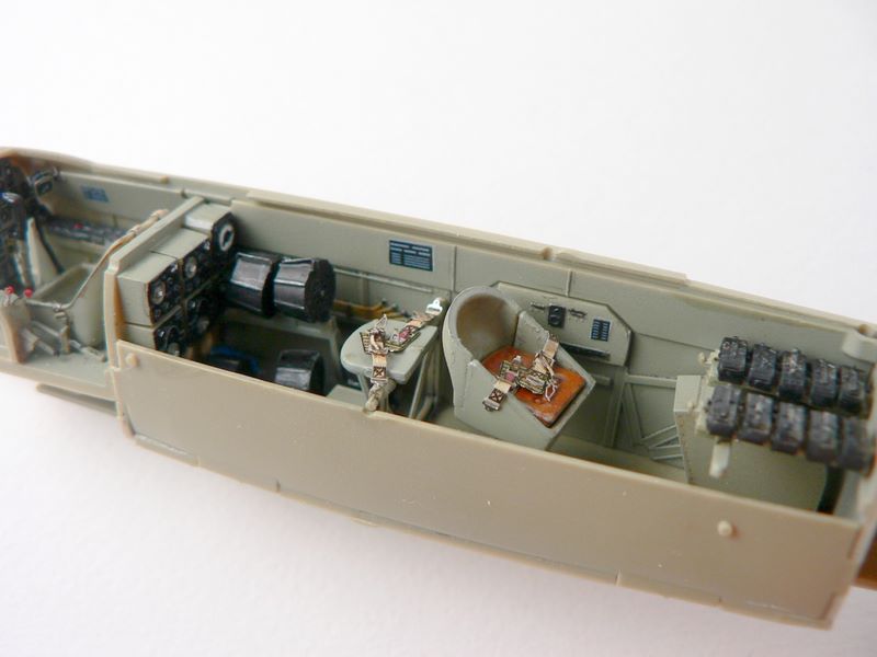
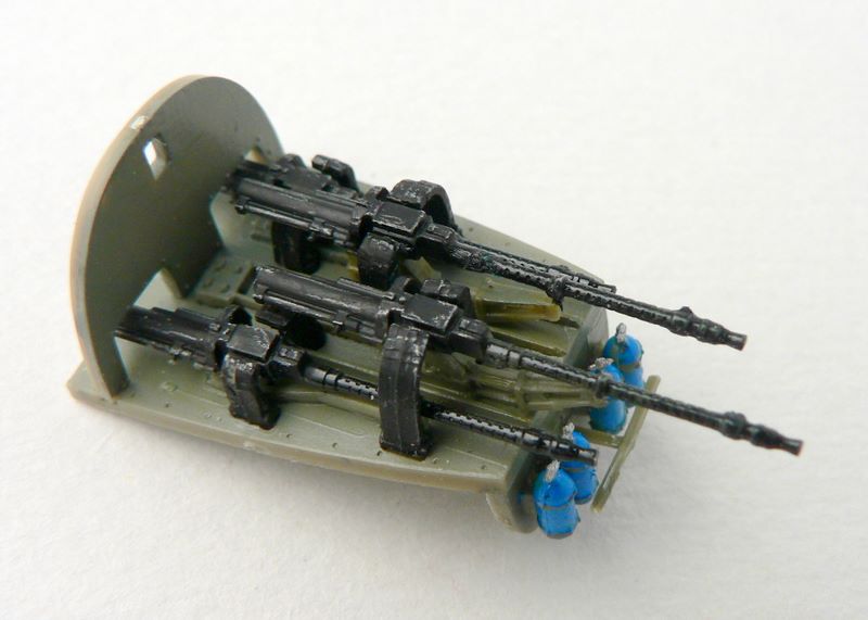
We then move onto the gunner and radio operator station. Ammunition drums and bottle are provided. The bright blue color of the bottles adds a bit of life to an otherwise gray area. Machine guns are also provided for mounting underneath the floor, but it will be almost completely hidden once the fuselage is closed up. The ammunition drums at the radio operator station are a bit of a tight fit and they have no locating pins where they attach to their mounts. You may want to install the mounts (parts G61 & G77) onto the cockpit floor before gluing on the drums to make sure everything fits into place. The gunner seat is meant to swivel, but I decided to glue my in place.
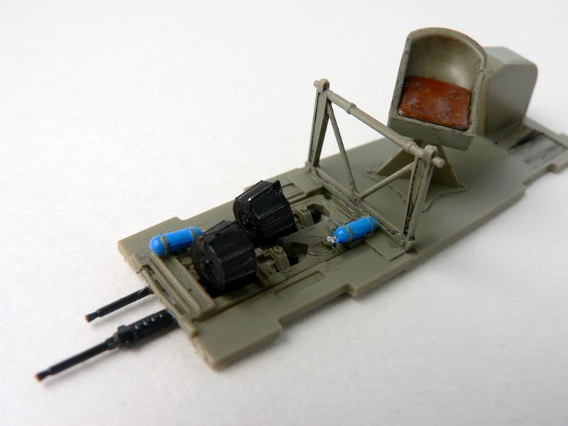
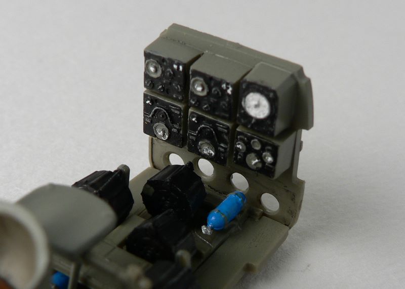
You also have the option of having the radio operator’s seat up or folded. The radio stack is made from plastic with well defined raised details. Using very dark gray for the panels, I picked out the larger details with white paint and finished it off with a rubbing onto all the edges from an artist silver pencil .
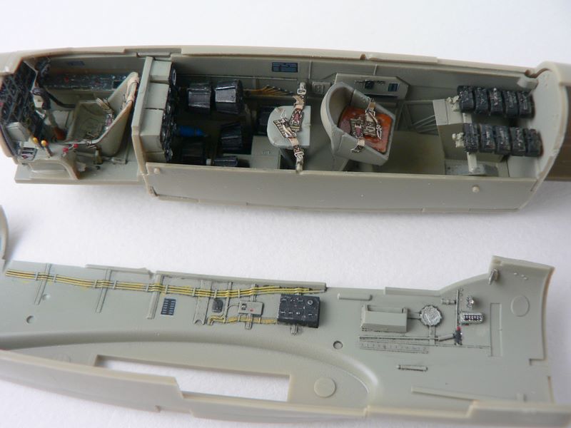
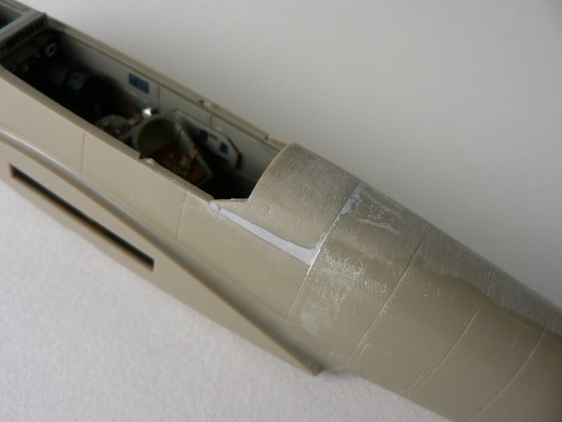
The sidewalls were then painted with RLM 02, the same color that was applied to most of the cockpit interior. The wiring was painted yellow and everything was given a wash of heavily thinned artist black oil paint. After everything was dried overnight, I added the PE seatbelts and joined the cockpit’s front and rear together along with the right side wall (photo 9). The rear gunner’s magazines were then added to the rear most area against the back wall. These magazines are each molded individually with an additional small PE piece. While the instruction initially shows 6 drums, only 5 really fit. If you look at the drawings immediately after the magazine assembly, you will realize only 5 are shown. However, be forewarned that after everything is closed up, most of these magazines will be completely hidden. If you are of the school where you only build what you can see, then you can safely leave off 3 magazines from each side and no one will be the wiser. The PE strip for each magazine will also be covered once finished.
At this point, I decided the cockpit walls needed a bit more to make it look busy so I added some Reheat placard decals. The upper right sidewall was painted, washed with oil, and detailed with PE. With the addition of the cockpit lower right wall, the cockpit was ready to be closed up.
The instruction calls for attaching the front of the cockpit to the rear as one piece before sandwiching the assembly with the fuselage. First, be aware the front naturally attaches at a small slanting angle, don’t think you have made a mistake. Despite my doubt about its fit, the fuselage closed up nicely as per the instructions. Note that the two panel inserts (parts B9 and B16) are provided for the bottom gun bays. While not explicitly shown in the instructions, these panels have an overlapping lip which dictates that they are glued at the same time the fuselage is glued up.
Do not assume you can attach them afterwards as I almost did. The rear panel on my sample had a slight gap which was easily filled. But if you elect later on to attach the optional belly bomb, this panel is completely hidden and you need not worry about its appearance. The final step in the fuselage is the rear insert which covers most of the rear gunner’s ammunition drums. A bit of filler is needed here to make everything smooth . I’ve elected not to follow the directions to install the rear machine gun at this time – as it will be just begging to be broken later on.
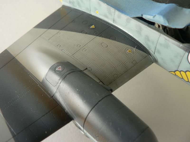
The engine nacelles were the next area to be built. Some of the parts look interchangeable, but they are not. So either take them off as you need them or mark them clearly to make sure you don’t glue the wrong pieces together. It is here that I had the most trouble with the kit. The nacelles simply did not fit well onto the wings. There is a slight step on the top, and a fairly large gap at the bottom rear. The step is a bit annoying as you will lose some details when trying to send that smooth. There is nothing here that cannot be fixed with filler and sanding, but it comes as a bit of surprise after how well everything has been fitting so far. The interior was again painted with RML 02 and washed with oil paint. There are some very good details molded in. At first I thought about adding some wiring details here but looking up some references realized that there just weren’t many exposed wires on the real plane, so I left everything alone. At this point I decided to deviate from the instructions and leave the landing gear area alone until the major building and painting were done. Again deviating from the instructions, I left the exhausts out until later on for easier painting. One word of caution here is that the exhaust backing is a very tight fit, after painting the paint layer will most likely prevent you from fitting the exhausts into its slot. Since the exhaust is somewhat fragile at this point, sand down the exhaust backing first to make sure you have enough room later on.
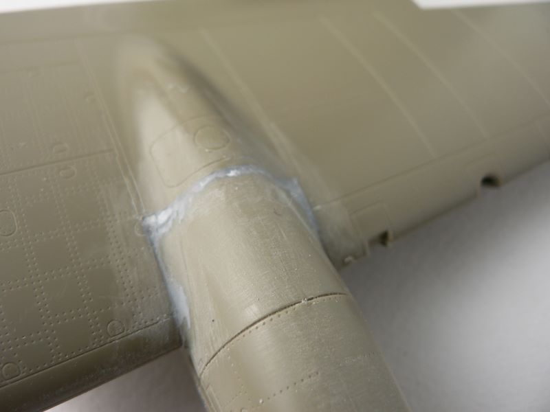
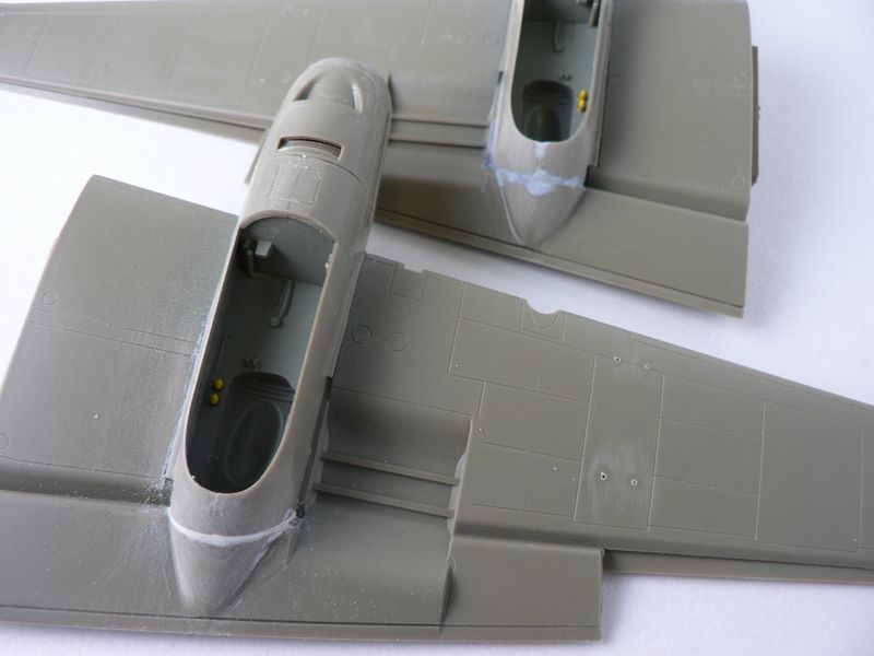
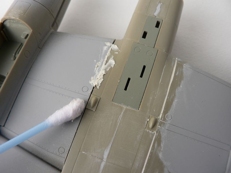
Attaching the wings themselves will show a somewhat poor fit. But before deciding on fillers to solve the problem, careful examination will show that the locating tabs are a bit long and the wing mating areas is not sufficiently flat. Some aggressive sanding at the tab and the mating areas will improve the fit tremendously. A bit of small filler was still needed in the bottom joint. With small gaps like these, I like to use Squadron white filler followed immediately by repeated wiping with a cotton swap that has been soaked with acetone based nail polish remover (photo 17). This method has the advantage of not losing any details due to sanding and much quicker than multiple drying/sanding. The ailerons are molded separately and needed a bit of sanding to fit. The separate molding gives a great sense of depth but does make the wings more delicate to handle as the ailerons are easily snapped off – I won’t tell you how many times I forgot that piece of advice. The rear wing actually fitted very well and almost snaps into place.
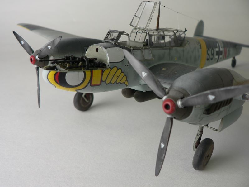
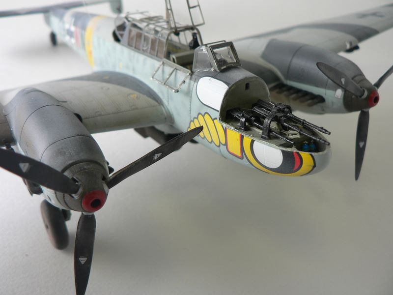
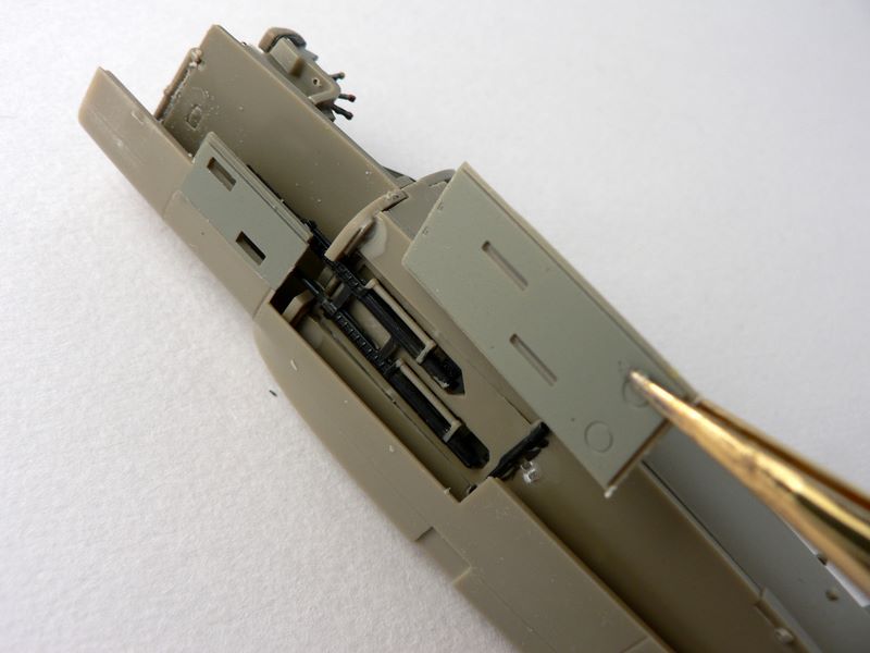
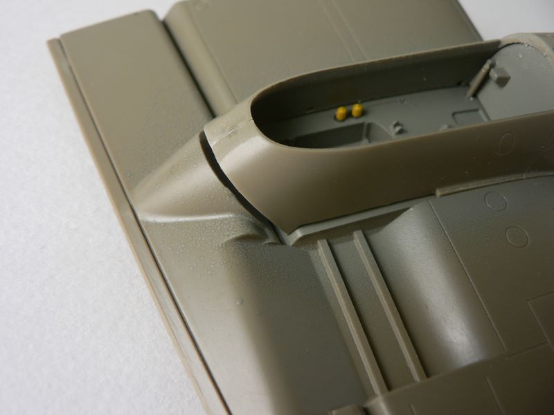
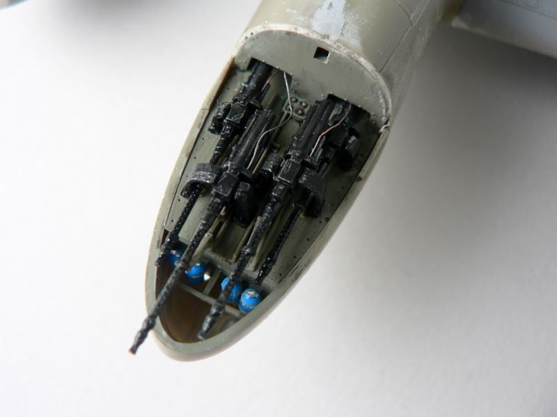
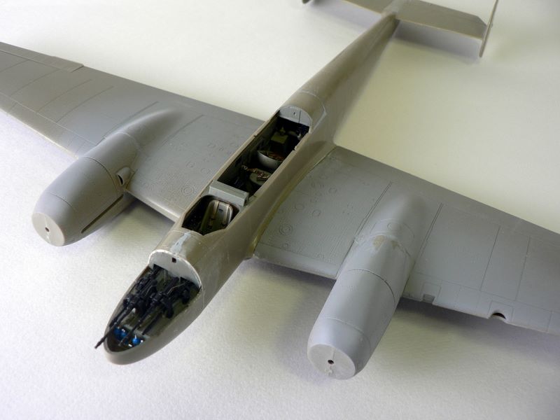
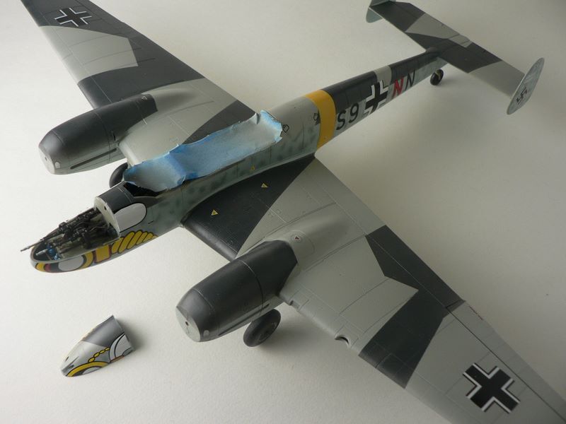
Next up is the nose gun bay. As supplied it has enough details to display open as is. However, I decided to add a few wires that are very evident in my reference photographs. The interior was painted with RML 02, the guns were painted Gun Metal, and the bottles were painted bright blue. Everything was given a black oil wash to pop out the details.
Once fitted, the nose can be mounted into the fuselage. The rear wall (part C10) of the gun bay does cause the nose to bulge out a bit which required some sanding to fix. If you decide to build yours with the gun bay closed up, I would advise leaving the rear wall out entirely (photo 19, 20).
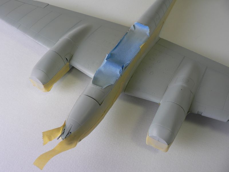
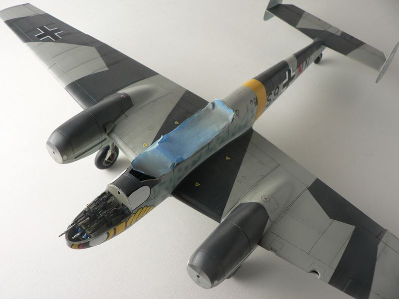
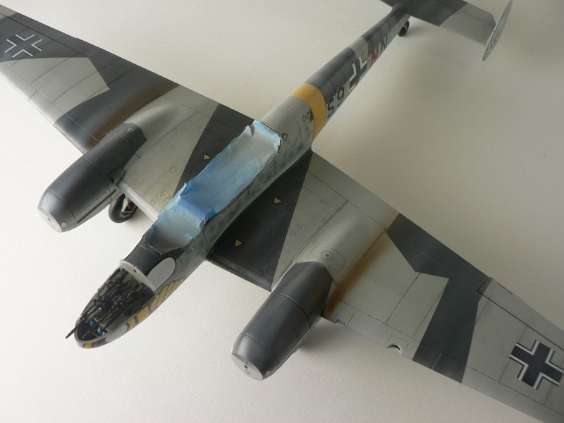
At this point, all the major parts have been built. Everything else was either really small and delicate parts or a part that would interfere with painting. So I deviated from the instructions and taped up the cockpit area and lay down a coat of Tamiya gray primer in preparation for painting.
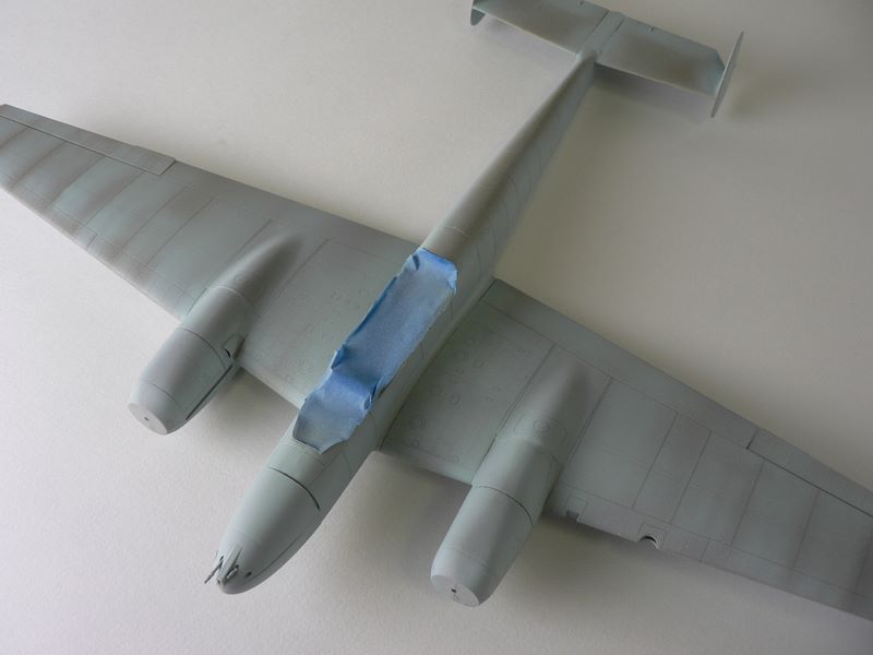
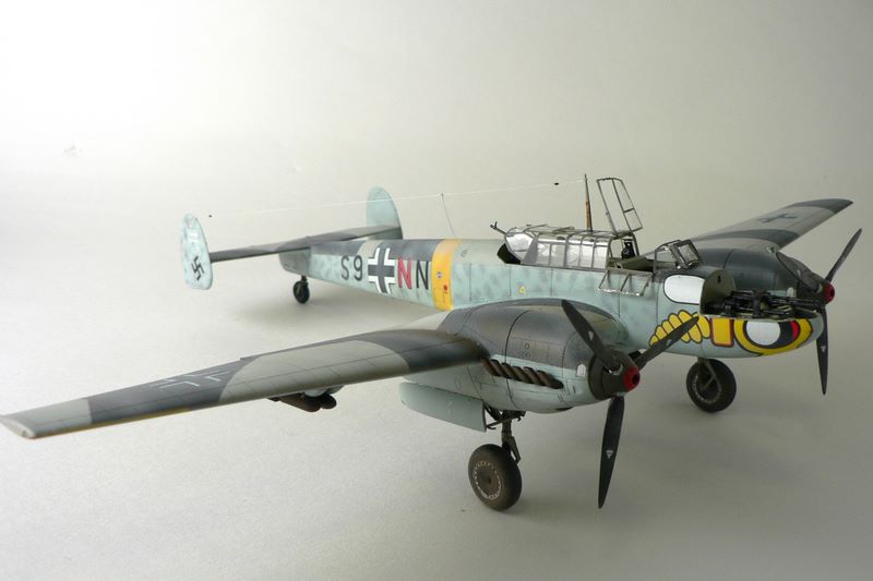
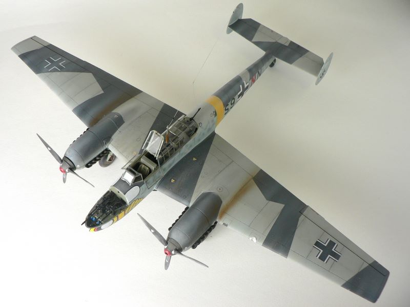
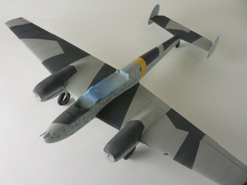
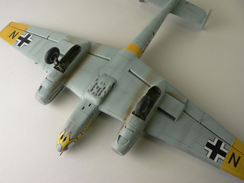
I realized that I had sanded the rear fuselage smooth to make the two sides fit. However, the aircraft had a panel line there and needed to be rescribed. After fixing a few joints that were still visible I sprayed the underside with my own mixture of light gray blue for the RML 76. I decided to finish the plane in “Wespen” markings of Lt. Kutscha in Russia. As depicted in the instruction booklet, a winter white wash was called for, but I decided to depict it in the Luftwaffe splinter camo before the whitewash was applied. The colors called for are RLM 75 and RLM 74. There is some debate as to the exact colors of the bf110 in Russia, as the colors were often changed at the front, I bow to Eduard’s research and followed their colors.
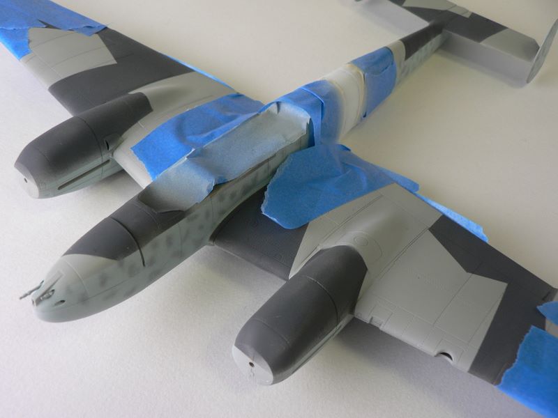
I first preshaded some panel areas with a dark gray and then masked off the sides with tape. I then sprayed a coat of RML 75 over the top wings, making sure to leave streaks of unevenness going from the front to the back. At this point I had already decided to make a dirty plane but not a worn one – similar to your automobile left outside after a few snowstorms. So there will be a minimum of fading or exposed metal. I then masked with more tape and lay down the dark gray, again leaving unevenness in the paint. I like to weather the plane as a whole instead of individual panels, as this gives a more realistic look to my eyes. I then loaded some slightly darker RLM 75 and applied the mottles to the sides.
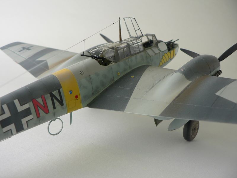
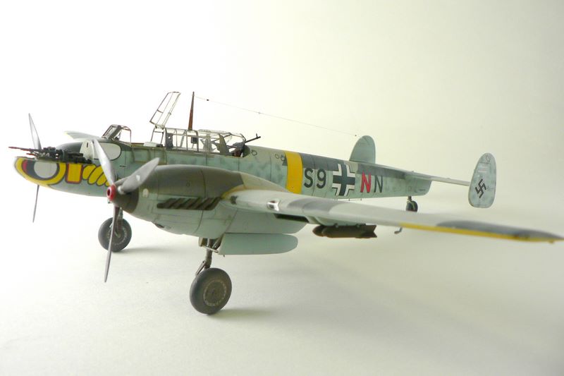
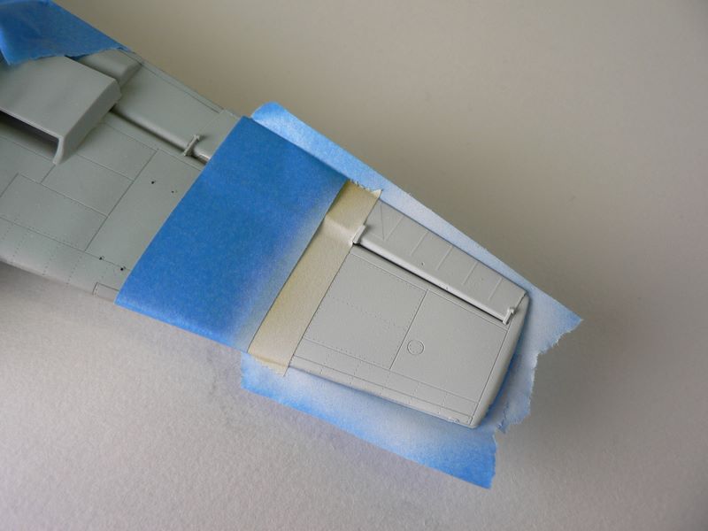
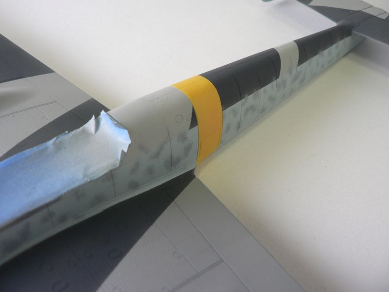
At this point, I realized that the yellow band around the fuselage needed to be painted and is not supplied as a decal. So I masked that off and lay down a coat of paint (photo 23), as yellow is notorious for bad coverage.
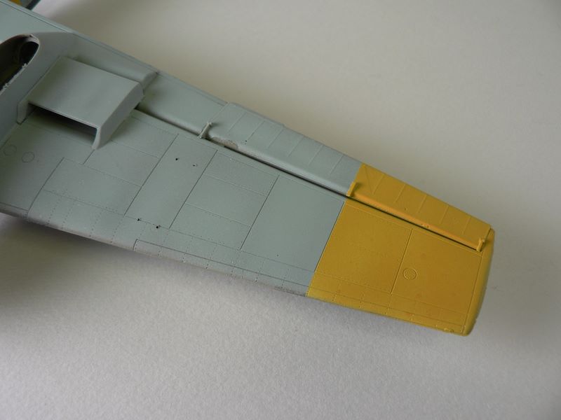
If I had to do this over again, I would have lay down the white paint before the splinter grays. But luckily after the yellow was on, it did not require too thick a coat before the grays were covered. The same yellow on white had to be done for the lower wing tips (photo 25, 26).
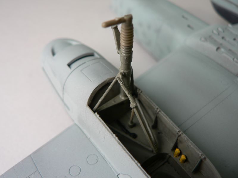
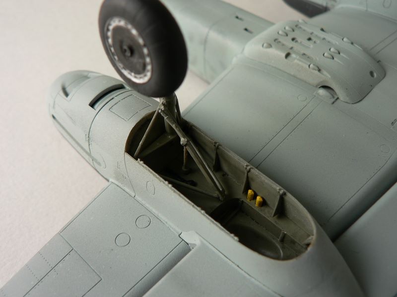
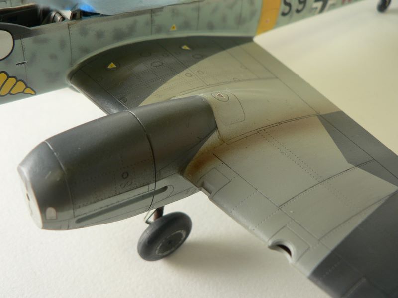
Back to fitting the landing gear. The parts are small and thin, so be careful taking them off the tree. The landing strut simply butt joins into the nacelle and depends on the thin supporting rods to stabilize it. With my sometimes heavy handling of my models, I knew that this arrangement would eventually break. I decided to drill a small locating whole into the nacelle area , and a corresponding hole in the strut. I then inserted a small stiff wire into the strut (photo 28) and attached the assembly into the nacelle with CA glue
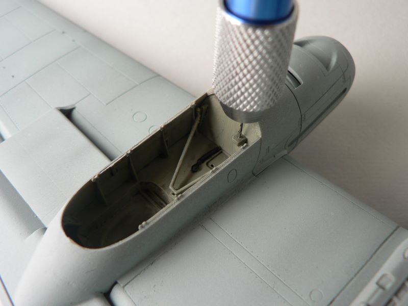
This creates quite a strong bond and minimizes any chance of breakage. The instruction originally advises the builder to leave off the landing gear doors until the nacelle is attached to the wing. I would advise leaving them off altogether until the very end. These have very small attachment points and can easily be snapped off.
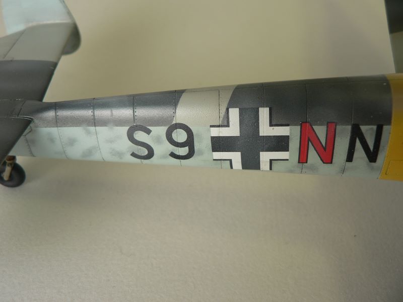
Forging on, I sprayed a coat of undiluted Future acrylic floor polish over the entire plane in preparation for the decals After letting the Future harden overnight, I put down the decals across a couple of nights as there are a whole set of stencils as well. I choose not to put every stencil down as these were often covered up in the field.
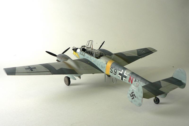
To give it that dirty wintry look, I added some white to my RLM 75 and thinned it at a 50/50 ratio. I then sprayed the aircraft in a somewhat random fashion, always taking the wind effect into account. I sprayed very light coats over the decals to tone them and blend them in with the rest of the plane. Next is a wash of thinned black oil paint. I like to load up the wash in a small brush and let capillary action carry the wash directly into each panel line.
Excess is simply wiped off and I can always add more if needed. While this takes a bit more time, I find it gives me better control over the effect. I then use some dilute brown oil wash to highlight specific areas that would have seen more wear such as the wing root areas. I used my airbrush to paint a mixture of diluted Tamiya brown and smoke as exhaust stain to both the top and bottom of the wing. Concentrating the spray more in the front, I then quickly moved my brush back and away to create the fading effect.
The plane is now over sprayed in somewhat random streaky fashion with a very thin layer of light gray paint. This included spraying the decals to meld them into the rest of the finish. The underside was given the same treatment.The side decals was also lightened, you can see how well the decals settled in here.
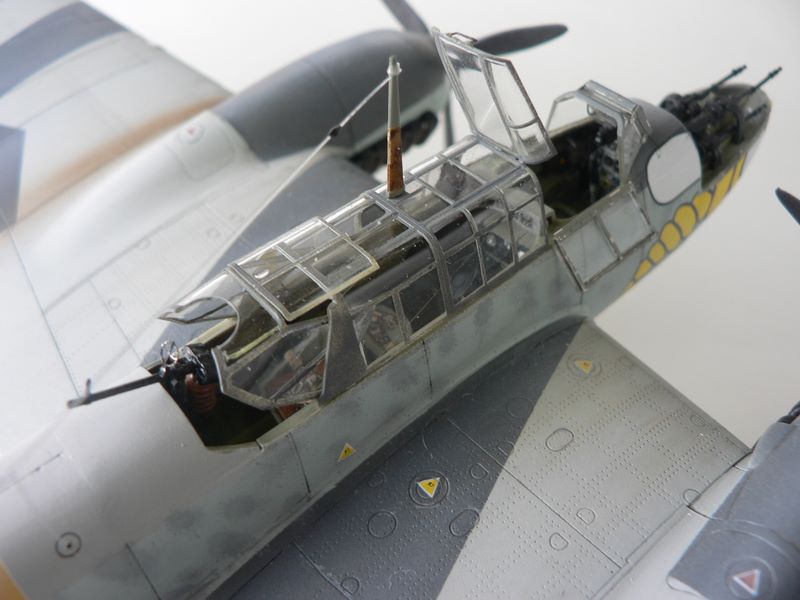
The main assembly was now done and the small parts needed to be painted and attached. First up is the canopy and as mentioned the supplied masking was a great labor saver.
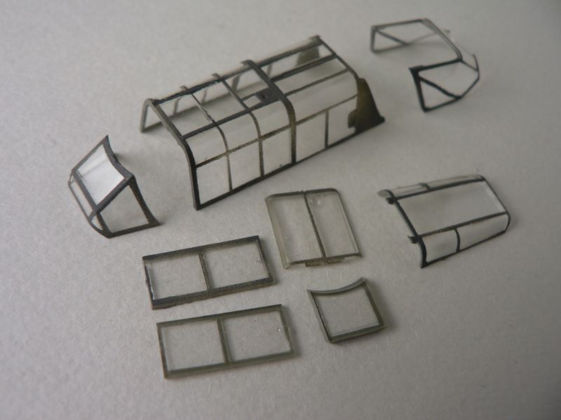
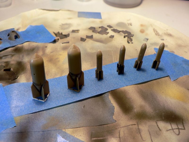
There are some very, very small PE handles to be attached, but looks wonderful if you make the effort. I then painted the bombs by attaching them to a strip of masking tape. On the far left, if you look closely you can see the bomb has white plastic strips on the bottom (photo 41). This was one of the repairs to very small parts to simply broke when I was not careful taking them off. The rear machine gun was attached with its wonderful PE gun sight (photo 42).
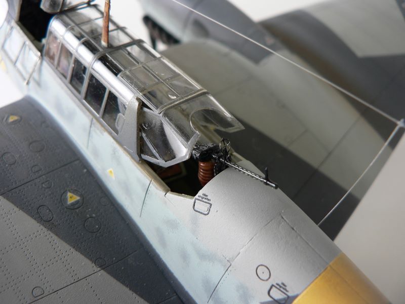
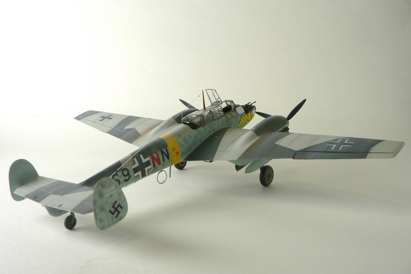
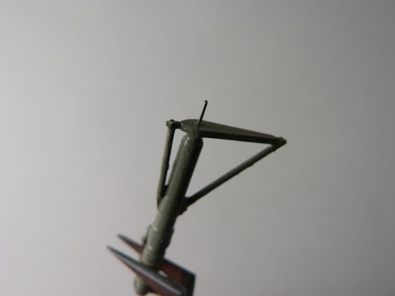
My mistake here was in attaching the canopy first before the rear gun, which made this a much more difficult exercise than it should have been. The final step was the antenna post and antenna made from fishing line. I first colored the line with a sliver marker and then drilled a very small hole in the rear stabilizer. After anchoring the line with CA glue in the hole I tied and fixed the line onto the post, snipping off the excess with small scissors (photo 43). I attached another antenna from the main line through a hole into the body of the plane that I had previously drilled. I then used small drops of CA glue to build up insulators at both ends of the antenna.
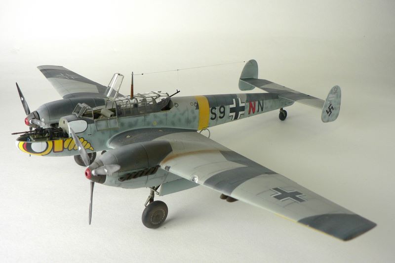
Finally, it was time to step back and admire my handiwork. The kit went together wonderfully, while the small parts and ill fitting engine nacelles required some work. It was easily overcome with some patience and care. Overall, it was a wonderful kit to build and I would recommend it to any intermediate level modeler.
My thanks to Eduard for the review kit.